


36
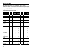
SCANNER PINOUT CONNECTIONS
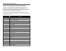
Version “2” Pin Assignments for Parallel Communication
The version “2” scanner head cable is terminated with a male 25-pin D-type
connector. Connecting the scanner to the host device may require a
communication cable. The communication cable may include a connection for a
transformer or it may be designed to draw power directly from the host device.
This can be ordered when the scanner is purchased.
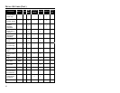
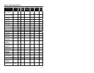
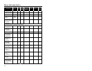
The version “2” scanner is designed to be used for Parallel communication.
The following is a list of the pin assignments. The pin numbers are impressed on
the head cable’s connector.
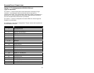
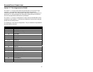
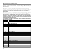
PIN FUNCTION
1 AC Shield Ground
2 RS-232 Receive Input
3 RS-232 Transmit Output
4 CTS Input
5 RTS Output
6 Reserved
7 Signal Ground
8 Reserved
9 Edit Check
10 EOT
11 Data Ready
12 Adaptor Ready
13 Earth Ground
14 Power Ground 1
15 Light Pen Source
16 Light Pen Data
17 Data 1
18 Data 2
19 Power (11 - 30 volts) DC
20 DTR Input
21 Data 3
22 Data 4
23 Data 5
24 Data 6
25 Power Ground 2