


51031604EN/AB - Page 5
Contents
1. Presentation
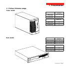
1.1 Pulsar EXtreme range................................................................................................................. 7
Tower model.................................................................................................................................... 7
Rack model ..................................................................................................................................... 7
1.2 Back ............................................................................................................................................. 8
Tower model.................................................................................................................................... 8
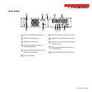
Rack model ..................................................................................................................................... 9
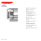
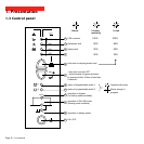
1.3 Control panel ............................................................................................................................... 10
2. Installation
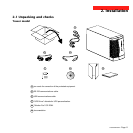
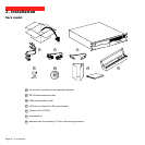
2.1 Unpacking and checks ............................................................................................................... 11
Tower model.................................................................................................................................. 11
Rack model ................................................................................................................................... 12
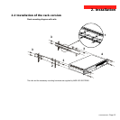
2.2 Installation of the rack version .................................................................................................. 13
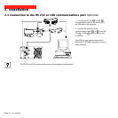
2.3 Connection to the RS 232 or USB communications port (optional)........................................ 14
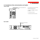
2.4 Installation of the communications-card option ...................................................................... 15
Tower model.................................................................................................................................. 15
Rack model ................................................................................................................................... 15
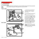
2.5 Connections ................................................................................................................................ 16
Tower model.................................................................................................................................. 16
Rack model ................................................................................................................................... 16
3. Operation
3.1 Start-up ........................................................................................................................................ 17
3.2 Bargraph indications .................................................................................................................. 17
3.3 Operation on battery power (following failure of AC input power) ............................................. 18
Transfer to battery power .............................................................................................................. 18
Threshold for the low-battery warning...........................................................................................18
End of backup time ....................................................................................................................... 18