


34007117EN/AB - Page 5
Contents
1. Presentation
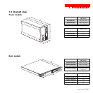
1.1 Overall view ................................................................................................................................. 7
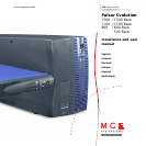
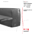
Tower models .................................................................................................................................. 7
Rack models ................................................................................................................................... 7
1.2 Back ............................................................................................................................................. 8
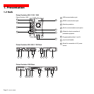
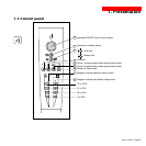
1.3 Control panel ................................................................................................................................. 9
2. Installation
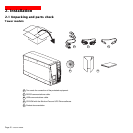
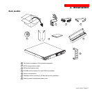
2.1 Unpacking and parts check ....................................................................................................... 10
Tower models ................................................................................................................................ 10
Rack models ................................................................................................................................. 11
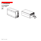
2.2 Installation ................................................................................................................................... 12
Tower models ................................................................................................................................ 12
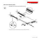
800/1100/1500 Rack models ........................................................................................................ 13
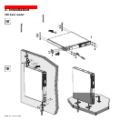
500 Rack model ............................................................................................................................ 14
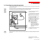
2.3 Connecting the protected equipment ....................................................................................... 15
2.4 Connection to the RS232 or USB communications port (optional)......................................... 16
2.5 Connection to the data-line protection port (optional) ............................................................. 16
2.6 Installation of the communications-card option ...................................................................... 17
3. Operation
3.1 Start-up ........................................................................................................................................ 18
3.2 Shift to booster or fader mode (during voltage variations in the AC-input power)..................... 18
3.3 Operation on battery power (following failure of AC-input power) ............................................. 19
Transfer to battery power .............................................................................................................. 19
Threshold for the low-battery warning...........................................................................................19
3.4 Personalisation (optional) ........................................................................................................... 20
Function ........................................................................................................................................ 20
ON / OFF conditions tab ............................................................................................................... 20
Battery tab..................................................................................................................................... 20
Voltage-thresholds tab .................................................................................................................. 21
Sensitivity tab ................................................................................................................................ 21