


MGE UPS SYSTEMS
Pulsar EX
Rack
: 86-153500-00 7
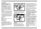
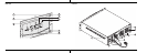
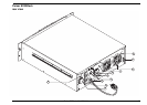
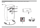
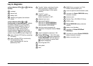
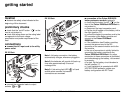
key to diagrams
2 "function" button: switches off audio
warning device or measures load
charge percentage (if utility power
present),
3 "ON/OFF" switch:
button pushed in: ON
button not pushed in: OFF,
5 attached input cord,
6 input circuit breaker:
20A/125V for Pulsar EX20
Rack
,
30A/125V for Pulsar EX30
Rack
, -
L5-20 EX20R, L5-30 EX30R,
7a twist-lock output receptacle for
connection of computer loads to Pulsar
EXR,
7b output receptacles rated each 15A,
7c Pulsar EX20
Rack
: T 15A/120V fuses
to protect each 7b output receptacles,
Pulsar EX30
Rack
: 15A/120V push to
reset circuit breakers to protect each
7b output receptacles,
8 site wiring fault LED,
9 rating label,
10 fans,
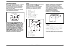
yellow indicator LEDs 1a to 1d flashing
quickly:
1a overload,
1b device fault,
1c battery fault,
1d operating on bypass (fault tolerant
mode),
yellow indicator LEDs 1a to 1d
continuously or flashing slowly: indicate
the battery charge level (if utility power
present) or remaining battery time (if no
utility power present). They may be on
continuously or flash slowly during a
transition period. By pressing the button
marked "function" 2 when utility power is
present, they indicate the load charge level.
1e green indicator LED flashing: operating
on battery,
1f green indicator LED on continuously:
load powered by UPS,
green indicator light off: load no
powered by UPS,
11 SUB-D 9 pin connector for U-Talk
RS232 communication port,
12 cover for optional communication cards,
13 connector for Pulsar EXB20/30 battery
extension module,
14 warranty card,
17 Solution-Pac
TM
CD-ROM, EX Driver
18 RS232 cable,
19 Pulsar EXB20/30 battery extension
module,
20 battery circuit-breaker,
21 connector to Pulsar EX20
Rack
/
EX30
Rack
,
22 connector for second Pulsar EXB20/30
battery extension module,
23 battery connection cord.