


64 MHz, 32-Bit Floating Point Central Processing Unit
1 Mbyte Memory, State Logic
GFK-1167B
PLC CPUs
2
August 1997
MEMORY
PROTECT
a45243
OPEN
REPLACEMENT
BATTERY
CONNECTOR
1 MBYTE
MEMORY BOARD
CSE 925
CURRENTLY
INSTALLED
BATTERY
CONNECTOR
MEMORY
PROTECT
KEY
SWITCH
Y
R
E
B
A
T
T
MODULE
IC697CSE925
LABEL
44A726758–148R01
SERIAL PORT
USE THIS MODULE
IN SLOT 1 ONLY
CSE 925
OFF
ON
TOP
REMOTE PROGRAMMER
MODULE OK
RUN
OUTPUTS
ENABLED
ON = OK, ENABLED,
PROTECTED
FRONT
RUN WITH
OUTPUTS
ENABLED
RUN WITH
OUTPUTS
DISABLED
STOP
KEY POSITION
MODULE FUNCTION
BATTERY
CONNECTORS
INSTALL NEW
BATTERY BEFORE
UNPLUGGING OLD
BATTERY. USE
IC697ACC701
MEMORY PROTECT
REMOTE
PROGRAMMER
ONLY
RS-485
COMPATIBLE
64 MHz 32 BIT CENTRAL
PROCESSING UNIT WITH
FLOATING POINT MATH
COPROCESSOR, IN-SYSTEM
UPGRADABLE FIRMWARE
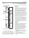
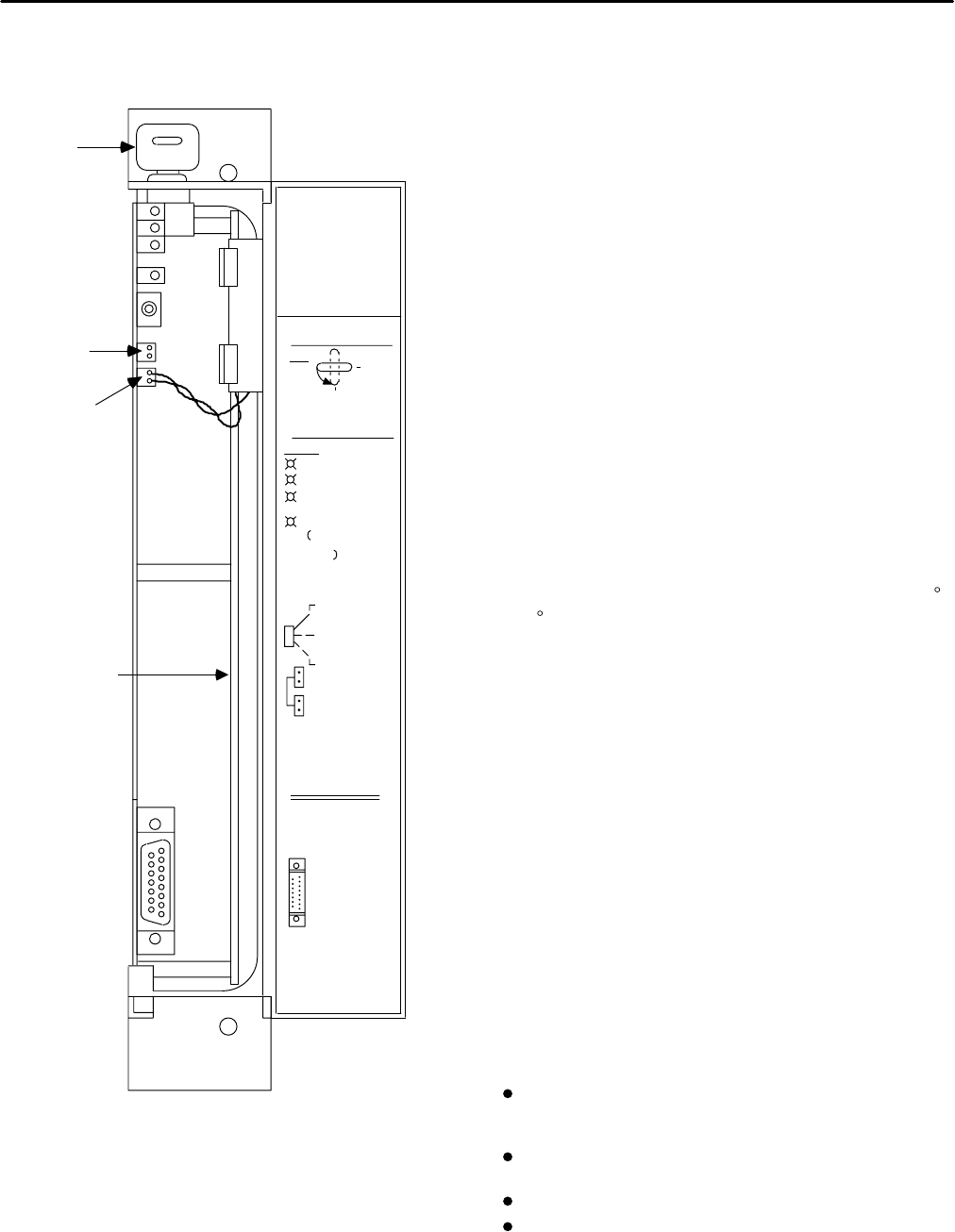
Figure 1. CSE 925 - Location of Major Features
Supported option modules include IC697 LAN Interface
modules, Programmable Coprocessor, Alphanumeric
Display Coprocessor, Bus Controller for IC660/IC661 I/O
products, Communications modules, I/O Link Interface,
and all of the IC697 family of discrete and analog I/O
modules.
User Memory
Program and data memory for the CSE 925 is provided by
a memory board with 1 Mbyte of battery-backed CMOS
RAM. This memory board is an integral part of the CSE
925 module and does not need to be ordered separately.
Operation, Protection, and Module Status
Operation of this module can be controlled by the
three-position RUN/STOP switch or remotely by an
attached programmer, and AD641 or IC641 (MS-DOS)
software. Program and configuration data can be locked
through software passwords or manually by the memory
protect keyswitch. When the key is in the protected
position, program and configuration data cannot be
changed. The status of a CPU is indicated by the four
green LEDs on the front of the module.
The CSE 925 requires forced air cooling for proper
operation in ambient temperatures greater than 40 C
(104 F). A fan capable of 70 CFM (including filters) should
be located beneath slot 1 of the rack containing the CPU.
Fan assemblies (IC697ACC 721 and IC697ACC724) can be
ordered for direct mounting on the IC697 rack. Refer to
the applicable Programmable Controller Installation Manual
for detailed information.
Installation
It is the responsibility of the OEM, system integrator, or
end user to properly install the PLC equipment for safe
and reliable operation. Product manuals provide
detailed information about installation, startup, and
proper use of the PLC equipment. The installation
manual, shipped with your PLC programming software,
describes how to properly install the equipment. If the
PLC installation must comply with supported standards,
such as FCC or CE Directives, please refer to the
Installation Requirements for Conformance to Standards,
shipped with the PLC programming software, for
additional guidelines.
Installation should not be attempted without refer-
ring to the applicable Programmable Controller Installa-
tion Manual.
Connect the battery to either of the battery connec-
tors on the module (see Figure 1).
Put the toggle switch in the STOP position.
Put the keyswitch in the Memory Protection OFF
position.