


3
64 MHz, 32-Bit Floating Point Central Processing Unit
1 Mbyte Memory, State Logic
GFK-1167B
PLC CPUs
August 1997
Make sure that rack power is off.
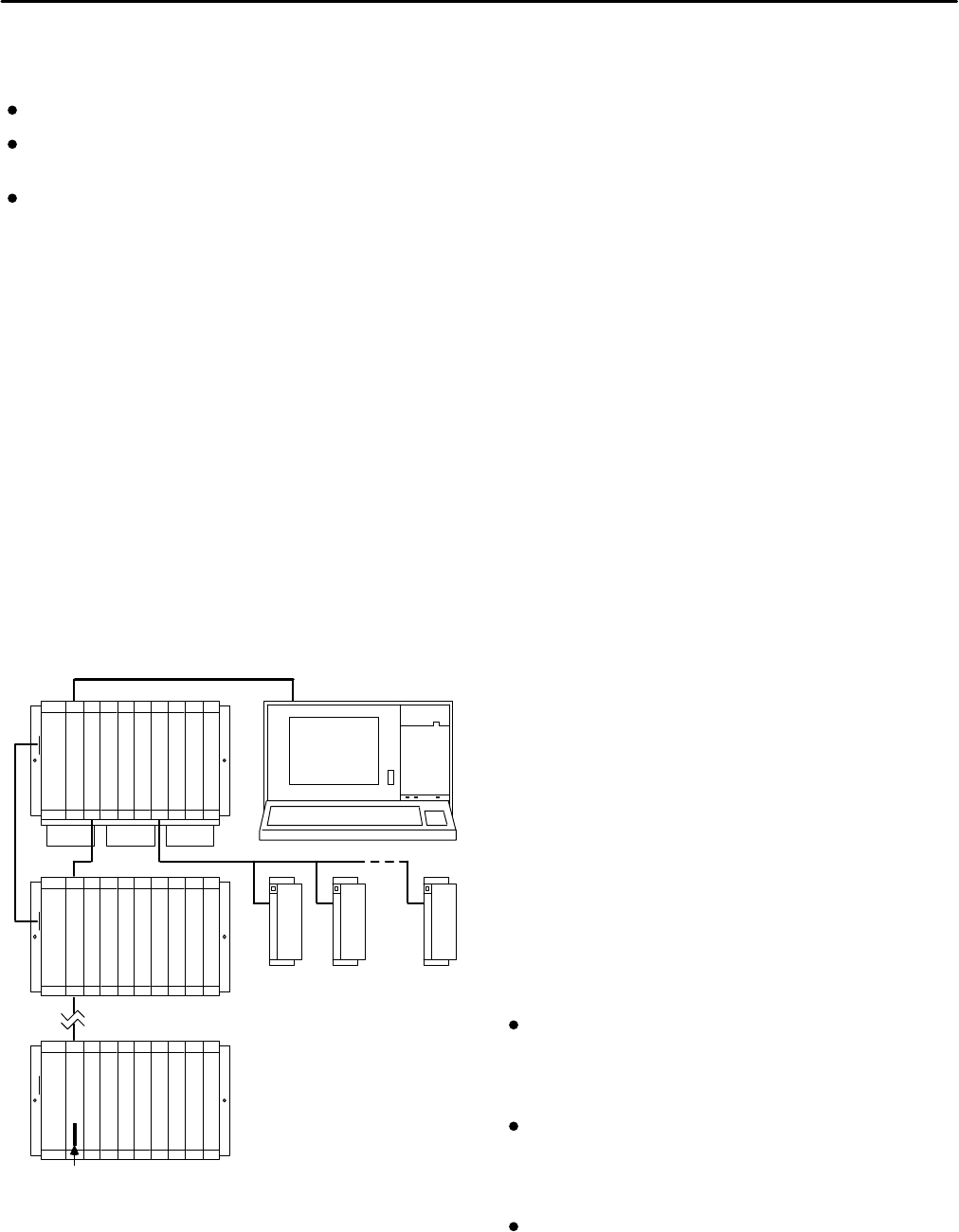
Install the CSE 925 module in slot 1 of rack 0 (see
Figure 2).
Turn on power.
The module should power up and the top LED should
blink. When the diagnostics have completed successfully,
the top LED stays on and the second and third LEDs are
off. The fourth LED is off if the keyswitch is in the OFF
position. The CPU is now ready to be programmed.
After the program has been verified the toggle switch may
be moved to the appropriate operation mode position.
The LEDs indicate the position of the toggle switch,
memory protection status, and the state of the program.
The IC641 (MS-DOS) software is also used to load the State
Logic operating system into the CSE 925 CPU module.
The operating system is provided on a floppy disk with
the CSE 925. The operating system is stored in flash
memory on the module. For information on loading the
operating system, see the State Logic Control System User’s
Manual.
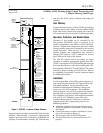
IC66* I/O BUS (7500 FEET (2285 METERS) MAXIMUM)
B
R
M
a45301
IC66*
I/O BLOCK
PROGRAMMER
RACK 1
RACK 0
P
S
C
P
U
B
T
M
G
B
C
B
R
M
RACK 7
ONE
METER
TOTAL LENGTH OF ALL INTERCONNECTING
CABLES FROM BTM TO LAST BRM IS
50 FEET(15 METERS) MAXIMUM. ALL RACKS
MUST BE AT SAME GROUND POTENTIAL
(8 RACKS MAXIMUM).
NOTE
SERIAL
TERMINATOR PLUG (IC697ACC702)
P
C
M
FORCED AIR COOLING REQUIRED FOR
PROPER OPERATION. REFER TO TEXT.
*
*
RACK FAN ASSEMBLY IC697ACC721/724
AVAILABLE FOR DIRECT MOUNTING ON
RACK.
or
N
B
C
Figure 2. System Configuration, Serial Connection to
Programmer
Serial Port
The 15-pin D-connector provides the connection to an
RS-485 compatible serial port on the CPU as shown in
Figure 2.
The serial connection is made from the serial port on the
CPU to the serial port on the programming computer, or
other serial device, through the RS-422/RS-485 to
RS-232 Converter (IC690ACC900) or RS-232 to RS-422
Miniconverter (IC690ACC901). This connection can be
made with available cables or you may build cables to fit
the needs of your particular application. See reference
3 for more information on serial communications.
Configuration
The IC697 CPU and I/O system is configured with IC641
(MS-DOS) programming software. There are no DIP
switches or jumpers used to configure the system. The
CPU verifies the actual module and rack configuration
at power-up and periodically during operation. The
actual configuration must be the same as the
programmed configuration. Deviations are reported to
the CPU alarm processor function for configured fault
response. Consult Reference 1 for a description of
configuration functions.
Batteries
A lithium battery (IC697ACC701) is installed as shown
in Figure 1. This battery maintains program and data
memory when power is removed and operates the
calendar clock. Be sure to install the new battery before
removing the old battery. Specific indication of a low
battery state is detailed in Reference 2.
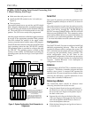
Removing a Module
The instructions below should be followed when
removing a module from its slot in a rack.
Grasp the board firmly at the top and bottom of
the board cover with your thumbs on the front of
the cover and your fingers on the plastic clips on
the back of the cover.
Squeeze the rack clips on the back of the cover
with your fingers to disengage the clip from the
rack rail and pull the board firmly to remove it
from the backplane connector.
Slide the board along the card guide and remove
it from the rack.