


2-9
Hardware Setup
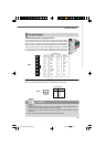
Power Supply
PIN SIGNAL
13 +3.3V
14 -12V
15 GND
16 PS-ON#
17 GND
18 GND
19 GND
20 Res
21 +5V
22 +5V
23 +5V
24 GND
PIN SIGNAL
1 +3.3V
2 +3.3V
3 GND
4 +5V
5 GND
6 +5V
7 GND
8 PWR OK
9 5VSB
10 +12V
11 +12V
12 +3.3V
Pin Definition
pin 12
pin 13
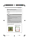
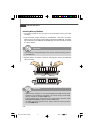
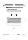
ATX 24-Pin Power Connector: ATX1
This connector allows you to connect an ATX 24-pin power supply.
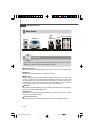
To connect the ATX 24-pin power supply, make sure the plug of the
power supply is inserted in the proper orientation and the pins are
aligned. Then push down the power supply firmly into the connector.
You may use the 20-pin ATX power supply as you like. If you’d like
to use the 20-pin ATX power supply, please plug your power sup-
ply along with pin 1 & pin 13 (refer to the image at the right hand).
ATX1
1
12
24
13
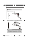
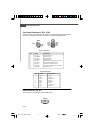
PIN SIGNAL
1 GND
2 GND
3 12V
4 12V
Pin Definition
JPW1
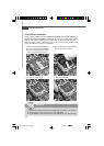
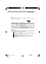
Important
1. Make sure that all the connectors are connected to proper ATX power sup-
plies to ensure stable operation of the mainboard.
2. Power supply of 350 watts (and above) is highly recommended for system
stability.
3. ATX 12V power connection should be greater than 18A.
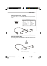
ATX 12V Power Connector: JPW1
This 12V power connector is used to provide power to the CPU.
1
3
4
2
7563v1.0CH2 Hardware Setup.p65 2008/11/11, 下午 05:369