


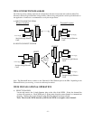
C. SIDE VIEW (cont’d)
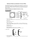
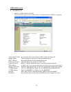
2. ETHERNET PORT
Standard RJ-45 connector.
3. ROTARY CHANNEL SELECT SWITCH
Shows switch settings for channels 0 – 9.
*Note: Channels 0, 1 and 2 are the same frequency. If two or more systems are in use and
either channel 0, 1 or 2 are used on the first system, the following systems must be set to
channel 3 or higher. If the second system is not set to channel 3 or higher, the two systems
could interfere with one another. When changing channels, power to each WEM must be
cycled for the WEM to recognize and operate on the new channel.
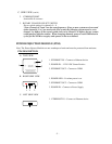
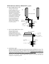
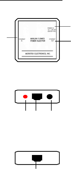
POWER INJECTION MODULE (PIM)
Note: The Power Injector Modules are not weatherproof units and must be protected from moisture.
PIM DESCRIPTION
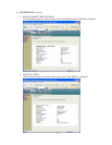
A. TOP VIEW
1. ETHERNET IN – Connect to Ethernet device
2. POWER IN – 12-20 VDC Center Positive
3. ETHERNET OUT – Connect to WEM
2
3
1
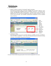
B. RIGHT SIDE VIEW
1. POWER LED – Lit when power is on
2. ETHERNET OUT – Connect to WEM
3. POWER IN – Connect to Power Supply
12 3
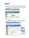
C. LEFT SIDE VIEW
1. ETHERNET IN – Connect to Ethernet device
1
- 5 -