FAULT ISOLATION and CORRECTION
If the E-FX-HB-xx00 fails, isolate and correct the fault by determining the
answers to the following questions and then taking the indicated action:
1. Is the P(o)W(e)R LED on the E-FX-HB-xx00 illuminated?
NO
• Is the power cord properly installed in the E-FX-HB-xx00 and in the
grounded AC outlet?
• Does the grounded AC outlet provide power?
• Contact Technical Support: (800) 260-1312.
YES
• Continue at step 2.
2. Is a backbone uplink adapter installed at E-FX-HB-xx00 back?
NO
• Continue at step 7.
YES
• Continue at step 3.
3. Is the B(ack)B(one) STAT(us) LED illuminated continuously?
YES
• Continue at step 7.
NO
• Continue at step 4.
4. Does the B(ack)B(one) STAT(us) LED blink on and off?
YES
• Ensure that backbone uplink adapter is firmly connected.
• Check backbone uplink cables for proper cabling and connection(s).
• Ensure that device at remote end of network link is powered.
• Contact Technical Support: (800) 260-1312.
NO
• Continue at step 5.
5. Is the B(ack)B(one) STAT(us) LED dark?
YES
• The port is partitioned or isolated; investigate the device at the far
end of the link.
• Contact Technical Support: (800) 260-1312.
NO
• Continue at step 6.
6. Is the B(ack)B(one) ACT(ivity) LED illuminated?
NO
• Disconnect and reconnect the backbone cable to restart the
initialization process.
• Restart the attached network device to restart the initialization
process.
• Contact Technical Support: (800) 260-1312.
Optionally Install Backbone Uplink Adapter
WARNING: Remove AC line cord from power source before installing
backbone uplink adaptor in E-FX-HB-xx00. Failure to observe this warning
could result in personal injury or death.
CAUTION: Wear a grounding device and observe electrostatic discharge
precautions when installing backbone uplink adaptor in the E-FX-HB-xx00.
Failure to observe this caution could result in damage to, and subsequent
failure of, backbone uplink adaptor.
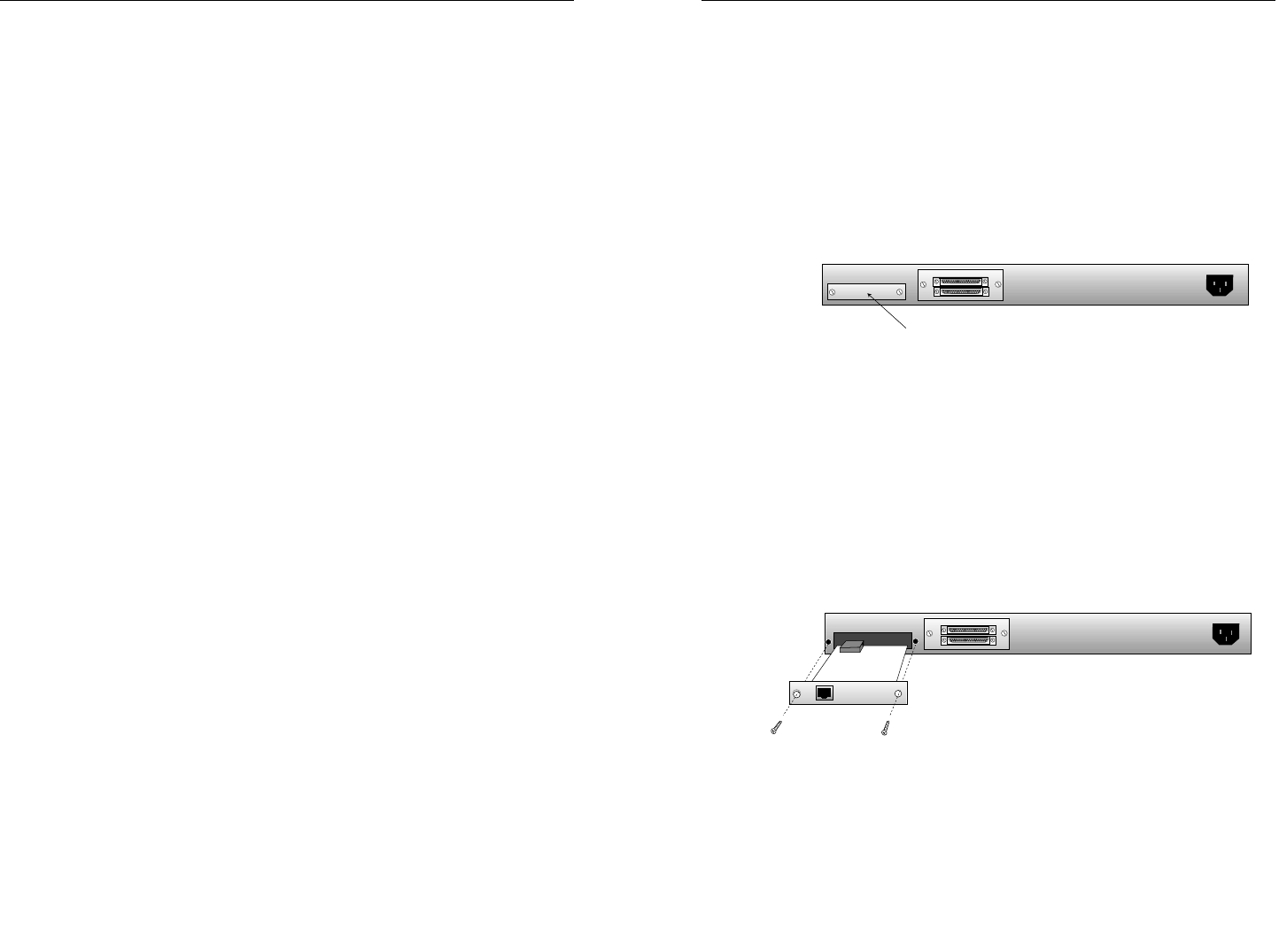
To install the backbone uplink adapter in the E-FX-HB-xx00:
1. Locate backbone uplink adapter plate at back of E-FX-HB-xx00.
2. Remove backbone uplink adapter plate by using flatblade
screwdriver to remove two (2) screws that secure backbone uplink
adapter plate to back of E-FX-HB-xx00.
NOTE: Retain screws for step 5. (Optionally discard backbone
uplink adapter plate.)
3. Carefully slide backbone uplink adapter, component side up, into
installation space revealed by removal of backbone uplink adapter
plate.
CAUTION: Do NOT force connection. Failure to observe this caution
could result in equipment damage and subsequent failure.
4. Press component on backbone uplink adapter securely against
internal mating E-FX-HB-xx00 component until backbone uplink
adapter faceplate is flat against E-FX-HB-xx00 back.
5. Secure backbone uplink adapter by installing retained screws
through backbone uplink adapter into E-FX-HB-xx00 chassis back.
Backbone Uplink Adapter Plate


