


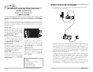
INSTALLATION
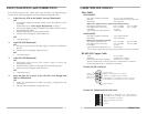
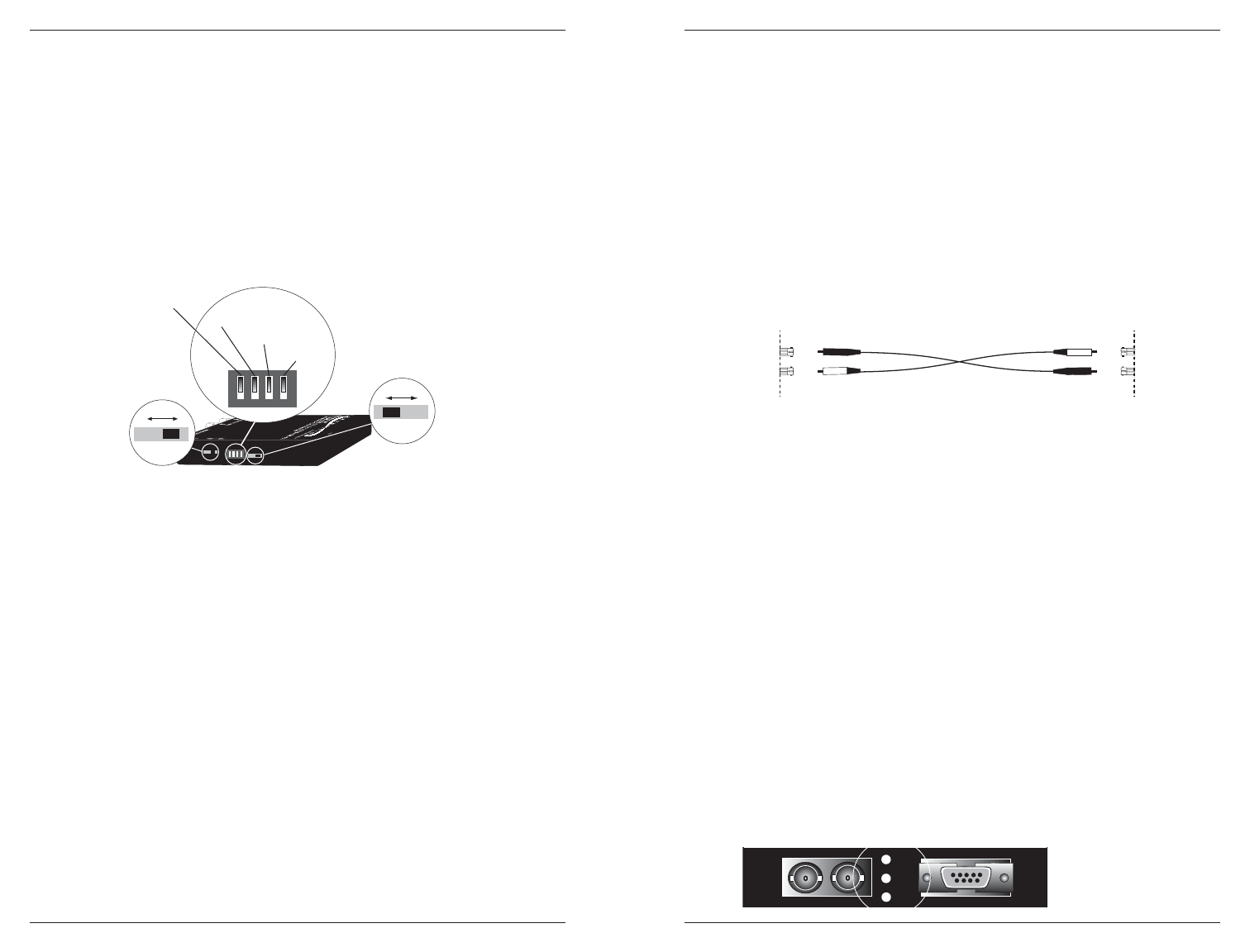
Set Switches
Use small flatblade screwdriver or similar device to set recessed switches
according to site installation.
1. Set the 2-wire /4-wire slide switch to the 4-wire setting to enable the
"receive – RS485 4 wire, RS422 and receive + RS485 4 wire, RS422"
pair for RS422 4 wire full duplex operation.
2. Set the RS-485/RS-422 slide switch to the RS-485 position to prevent
echo in two-wire mode. Set the RS-485/RS-422 slide switch to the RS-
422 to allow transmit only on "transmit/receive - (B) RS-485 2wire,
transmit - RS-422 and transmit/receive + (A) RS-485 2wire, transmit +
RS-422" pair.
3. Refer to drawing and to notes below for setting 4-position DIP switch.
* Position 1 ON inserts 130 ohm terminator on the "receive – RS485
4 wire, RS422 and receive + RS485 4 wire, RS422" pair.
** Position 2 ON inserts 130 ohm terminator on the "transmit/receive -
(B) RS485 2wire, transmit - RS422 and transmit/receive + (A) RS485
2wire, transmit + RS422" pair.
*** Position 3 ON enables 1K ohm pull
down
on "transmit/receive - (B)
RS485 2wire, transmit - RS422".
**** Position 4 ON enables 1K ohm pull
up
on "transmit/receive + (A)
RS485 2wire, transmit + RS422
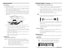
Install Cable
COPPER /DB-9 CONNECTOR
NOTE: Shielded cables are required on the DB-9 for EMC compliance.
1. Locate or build TIA/EIA-574-DB-9 compliant cables configured as
shown on page 6, with a male DB-9 connector at one end of
cable and with a straight-through cable.
2. Connect the male DB-9 connector at one end of cable to the
Media Converter female DB-9 connector.
3. Connect the other end of cable to the node device.
3
MDI
MDI-X
E-100BTX-FX-O4
9V DC Input
Config
Switches
1 2 3 4
RS-485
RS-422
DOWN=ON Inserts 130 resistor on "receive"*
DOWN=ON Inserts 130 resistor on "transmit"**
DOWN=ON Enables 1K "pull-down"***
DOWN=ON Enables 1K "pull-up"***
*
1
2
3
4
2-wire
4-wire
INSTALLATION -- Continued
COPPER /TERMINAL BLOCK CONNECTOR
1. Locate or build TIA/EIA-574-compliant terminal block cables
configured as shown on page 6 and with straight-through cable.
2. Using a small flatblade screwdriver or a similar device, release each
terminal block installation location as necessary. Refer to the
diagram on page 6, connect the wires at one end of cable to the
Media Converter terminal block connector.
3. Connect the other end of the cable to the node device.
FIBER
1. Locate or build TIA/EIA-574-compliant fiber cable with male two-
stranded TX to RX connectors at both ends.
2. Connect the male TX and RX cable connectors at one end of the
cable to the TX and RX female connectors, respectively, on the
Media Converter.
3. Connect the male TX and RX cable connectors at the other end of
the cable to the RX and TX connectors of the IEEE 802.3™
compliant fiber device.
Connect to Power
1. Install the power adapter cord at the back of the Media Converter.
2. Connect the power adapter plug to AC power.
3. Verify that the Media Converter is powered by observing the
illuminated LED(s).
OPERATION
After installation, the Media Converter should function without operator
intervention.
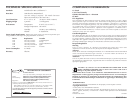
Status LEDs:
Use the status LEDs to monitor Media Converter operation in the network.
RXF Flashing LED indicates data reception on the fiber link.
RXC Flashing LED indicates data reception on the copper link.
P(o)W(e)R Steady LED indicates connection to external power.
RS485-CF-0x
4
Fiber
DB-9
RXF
RXF
RXC
RXC
PWR
PWR
T
X
R
X
TX
RX