


FAULT ISOLATION and CORRECTION
If the Media Converter fails, isolate and correct the failure by determining the
answers to the following questions and then taking the indicated action:
1. Is the P(o)w(e)r LED on the Media Converter illuminated?
NO
• Is the power adapter the proper voltage and cycle frequency for the
AC outlet?
NOTE: Refer to the “Power Supply Requirements” on page 7.
• Is the power adapter properly installed in the Media Converter and in
the grounded AC outlet?
• Does the grounded AC outlet provide power?
• Contact Technical Support at (800) 260-1312.
YES
• Proceed to step 2.
2. Is the RXF LED illuminated?
NO
• Disconnect and reconnect the fiber cable to restart the initialization
process.
• Contact Technical Support: (800) 260-1312.
YES
• Proceed to step 3.
3. Is the RXC LED illuminated?
NO
• Disconnect and reconnect the copper cable to restart the
initialization process.
• Restart the terminal device(s) to restart the initialization process.
• Contact Technical Support: (800) 260-1312.
YES
• Proceed to step 4.
4. Does the data fail to move across the link, even though both
LEDs are illuminated?
YES
• Check the RS-485/RS-422 cables for proper configuration and
connection.
• Contact Technical Support at (800) 260-1312.
5
CABLE SPECIFICATIONS
Fiber Cable
MULTIMODE
Fiber Optic Cable Recommended: 62.5 / 125 µm multimode fiber
Optional: 100/140, 85/125, 50/125 µm mm fiber
Wavelength: 850 nanometers
RS485-CF-01, RS485-CF-01(SC), RS485-CF-02, RS485-CF-02(SC):
Fiber Optic Transmitter Power: min: -16.0 dBm max: -10.0 dBm
Fiber Optic Receiver Sensitivity: min: -32.0 dBm max: -7.2 dBm
Link Budget: 16.0 dB
Typical Maximum Cable Distance**: 2 kilometers
SINGLEMODE
Fiber Optic Cable Recommended: 9 µm singlemode fiber
Wavelength: 1300 nanometers
RS485-CF-01(SM), RS485-CF-02(SM)
Fiber Optic Transmitter Power: min: -23.0 dBm max: -14.0 dBm
Fiber Optic Receiver Sensitivity: min: -34.0 dBm max: -14.0 dBm
Link Budget: 11.0 dB
Typical Maximum Cable Distance**: 20 kilometers
**Actual distance dependent upon physical characteristics of network installation.
RS-485/422 Copper Cable
Gauge 24 to 22 AWG
Attenuation 20 dB/1000’ @ 10 MHz
Differential Characteristic Impedance 100 Ω ±10% @ 10 MHz
Maximum Cable Distance varies by baud rate: 4000ft[1220M] at <90kbaud
decreasing logarithmically to 300ft[92M] at 500kbaud).
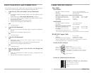
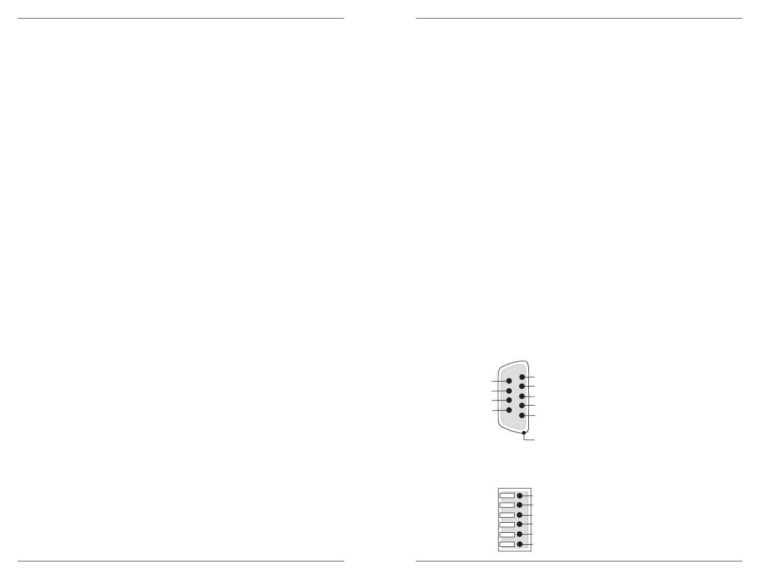
RS-485/422 DB-9 SIGNALS
RS-485/422 TERMINAL BLOCK SIGNALS
RS485-CF-0x
6
Not Used
Not Used
Receive (+) (A) RS-485 4-wire, (+) RS-422
Not Used
Not Used
Protective Ground
Transmit/Receive (-) (B) RS-485 2 or 4-wire, (-) RS-422
1
Signal Ground
5
Receive (-) (B) RS-485 4-wire, (-) RS-422
4
3
Transmit/Receive (+) (A) RS-485 2 or 4-wire, (+) RS-422
2
6
7
8
9
Ground
Ground
Receive (-) RS-485 4-wire, RS-422
Receive (+) RS-485 4-wire, RS-422
Transmit/Receive (-) (B) RS-485 2-wire, (-) RS-422 Transmit
6
2
3
4
5
1
Transmit/Receive (+) (A) RS-485 2-wire, (+) RS-422 Transmi
t