


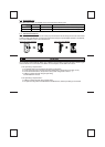
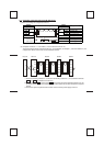
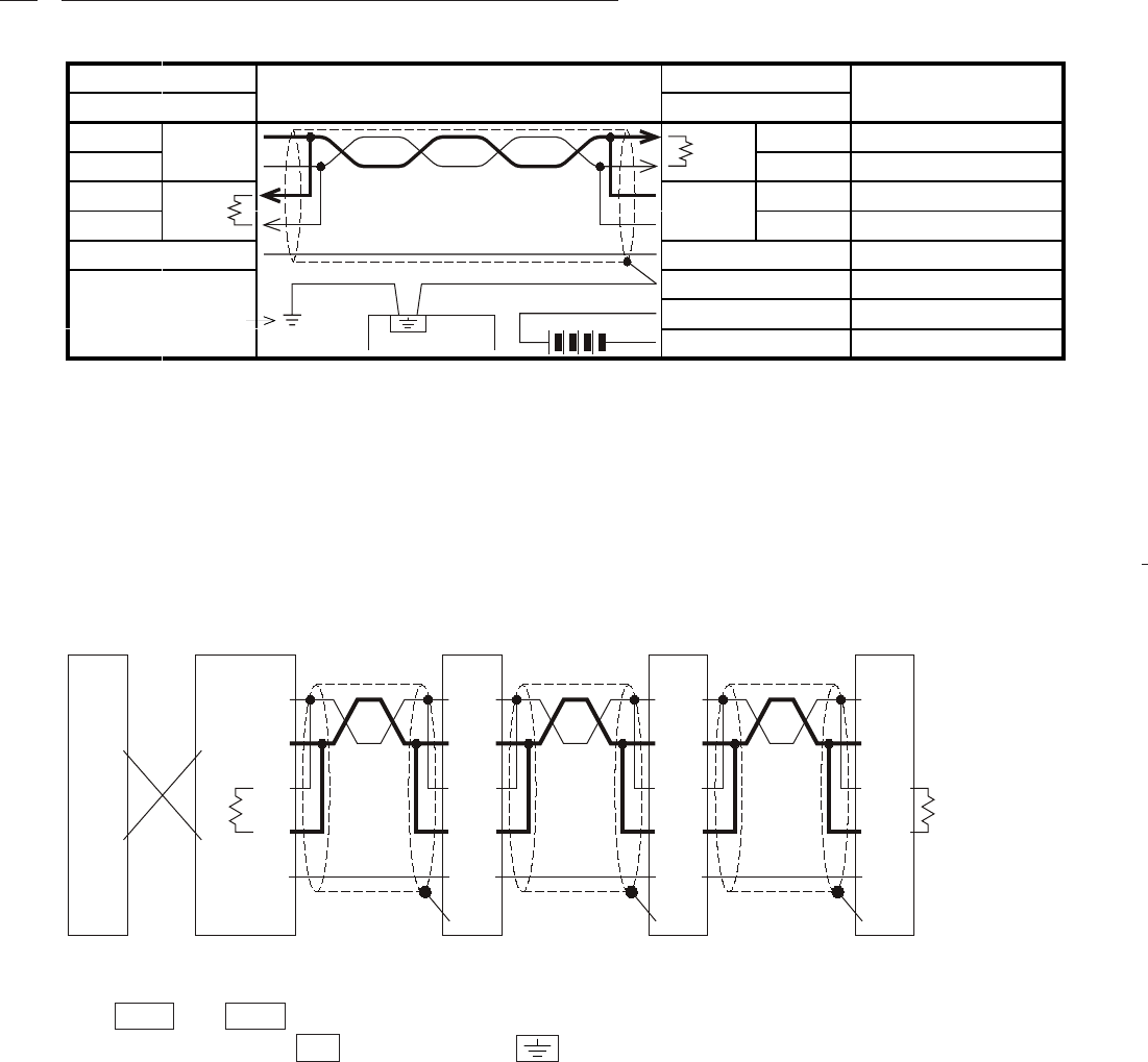
*1 R is the terminating resistance. Connect the terminating resistance (110 Ω) between terminals
RDA and RDB . For details see section 2.3.
*2 Connect terminal FG to earth terminal of the PC main body grounded with resistance of 100
Ω or less. However, as for the computer link unit of the A series PC, see the manual of the computer
link unit.
*3 The 24V DC power requirement can be taker from the service power supply of the PC.
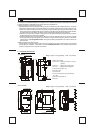
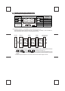
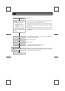
(1) When connecting one computer and one PC
485ADP485ADP485ADPComputer 485PC-IF
Station
No. 1
Station
No. 15
SDA
SDB
RDA
RDB
FG
SDA
SDB
RDA
RDB
FG
SDA
SDB
RDA
RDB
FG
SDA
SDB
RDA
RDB
R
*
1
SD
RD
SD
RD
R
*1
*2
*2*2
LINK
SG
LINK
SG
LINK
SG
Station
No. 0
LINK
SG
LINK SG
FG
24V
24G
LINK SG
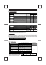
Cable connection and signal direction
485PC-IF
Signal name
Application
Reception data
Reception data
Transmission data
Transmission data
Signal ground
Frame ground
Power supply terminal
Power supply terminal
485ADP
Signal name
RDA
RDB
SDA
SDB
R
*1
SDA
SDB
RDA
RDB
R
*1
*2
*3
*3
2.2 Examples of one-pair wiring (for RS-485 circuit)
Grounding
resistance of
100 Ω or less
FX base unit
DC24V
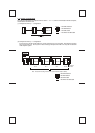
(2) Computer and PCs in 1 : n connection ( n has a maximum value of 16 ).
The terminal lagout shown is diagrammatic only. As for 485ADP, see chapter 1, and as for 485PC-IF, and
computer link unit for A series PC, see the individual manuals.