


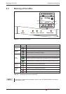
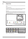

Setting the operating mode on the DIP switch
NOTE RS485 stipulates that thecables should be terminated at both ends ofthe transmission sec
-
tion. The termination prevents signal reflections in the cables and in times of no data trans
-
mission, enforces a defined idle state on the bus. This termination can be implemented
using, for example, specific resistors at the screw terminal. It can also be implemented via
the DIP switches on the Mitsubishi Alarm Modem.
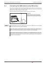
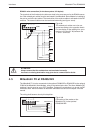
RS422 Connection
RS485 2-wire connection (2-wire bus system, half-duplex)
In this operating mode, transmit cables and receive cables are interconnected. If the Mitsubishi
Alarm Modem is installed at the beginning (first station) or end (last station) of the bus system,
the bus system must be terminated by setting the DIP switches accordingly.
RS485 / RS422 Interfaces
4-4 MITSUBISHI ELECTRIC
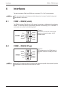
COM2
Device B
T–
T–
T+
T+
(0V)
R–
R–
R+
R+
Fig. 4-7:
The receiving lines are to be connected to
R+ (other end T+) and
R- (other end T-),
the sending lines to
T+ (other end R+) and
T- (other end R-)
according to the opposite sketch.
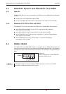
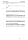
Operating mode DIP 1 DIP 2 DIP 3 DIP 4 DIP
Two-wire RS485 with termination 11111111
Two-wire RS485 without termination 00110011
Four-wire RS485 without termination 00000000
Four-wire RS485 with termination of receive cable 11001100
RS422 00000000
Tab. 4-1: Setting the operating mode on the DIP switch
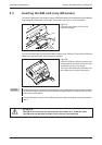
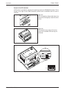
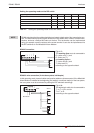
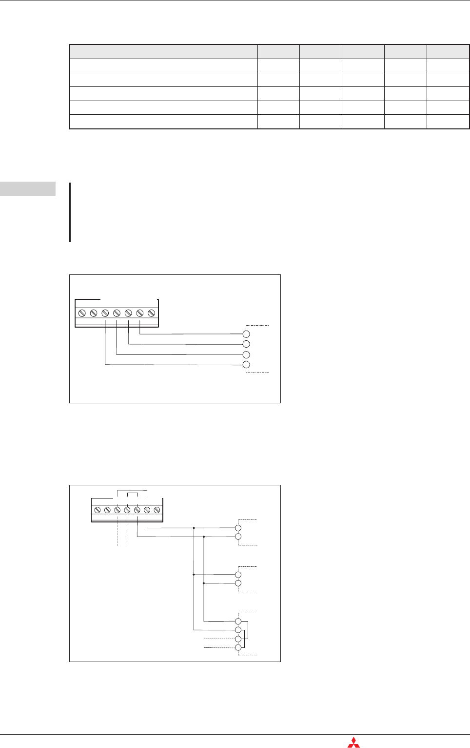
Bus Master
COM2
Slave 1
(0V)
R–/T–
R+/T+
Slave 2
R–/T–
R+/T+
Slave 3
R–
T–
R+
T+
T–
R–
T+
R+
Fig. 4-8:
The twisted pair cable is to be connected to
T+ to T+ or R+ and for
T- to T- o r R -
according to the opposite sketch.