


7
ENGLISH
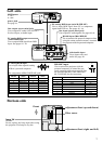
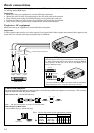
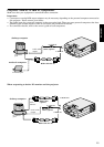
PC analog RGB input
Use to input video signals (analog
RGB) of a personal computer.
(Pin assignment of Mini D-SUB 15P jack)
PIN NO. SPEC PIN NO. SPEC
1 R(RED)/CR 9–
2
G(GREEN)/Y
10 GROUND
3
B(BLUE)/CB
11 GROUND
4 GROUND 12 –
5 GROUND 13 HD/CS
6 GROUND 14 VD
7 GROUND 15 –
8 GROUND
RS-232C input
Use to control the projector with the
personal computer, or control the per-
sonal computer with remote control. Use
the provided RS-232C cable (Mini DIN
8P– D-SUB 9P) for the connection.
PIN NO. NAME I/O
1 TXD IN
2 RTS IN
3 DTR IN
4 GND –
5 CTS/5V IN/OUT
6 DCD/CLOCK OUT
7 RXD OUT
8 RI/DATA OUT
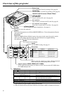
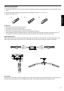
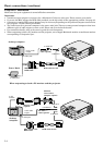
power jack
See page 11.
MAIN power
I : ON
O : OFF
RS-232 input (Mini DIN 8P)
Use to connect with personal computer when
using the remote control as mouse, or control
the projector with the personal computer.
line output (stereo mini jack)
Use to output PC audio if the PC has a
live-level input, or Audio input.
line input (stereo mini jack)
Use to input PC audio signals. See pages 13, 14.
PC analog RGB input (mini D-SUB 15P)
Use to input RGB signal from PC or component
signal from DVD etc. See pages 12 - 14.
video/audio input
Use to input video and
audio. See page 12.
PC analog RGB output
(mini D-SUB 15P)
Use to output RGB signal from RGB
input. See pages 12 - 14.
LINE-OUTRGB-OUT RGB-IN
S-VIDEO VIDEO
INPUT
L-AUDIO-R
LINE-IN
RS-232C
(MONO)
LINE-OUTRGB-OUT RGB-IN
S-VIDEO VIDEO
INPUT
L-AUDIO-R
LINE-IN
RS-232C
(MONO)
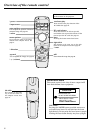
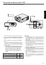
Bottom side
filter cover
adjustment foot (up and down)
adjustment foot (right and left)
Front
lamp lid
Caution:
Do not replace the lamp right after using
the projector. The lamp is very hot.
Left side
15
11 15
12
6 8
5
3