


E
20
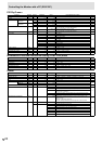
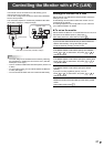
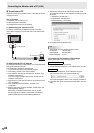
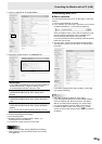
Controlling the Monitor with a PC (RS-232C)
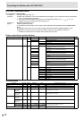
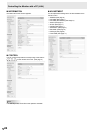
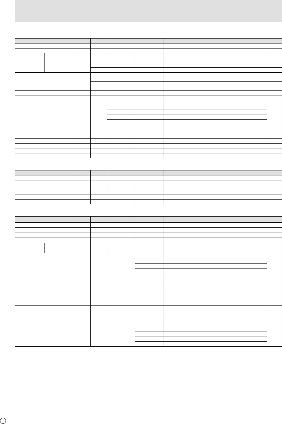
PIP/PbyP menu
Function
Command Direction
Parameter Reply Control/Response contents *
PIP MODES MWIN WR 0-3 0-3 0: OFF, 1: PIP, 2: PbyP, 3: PbyP2 B
PIP SIZE MPSZ WR 1-12 1-12 B
PIP POS THE LONGEST
DIRECTION
MHPS W 0-100 B
R 0-100 B
THE SHORTEST
DIRECTION
MVPS W 0-100 B
R 0-100 B
PIP POS LD+SD BATCH MPOS W 0-100,0-100 Specify the position in MPOSxxxyyy format.
(xxx: Longer side, yyy: Shorter side position)
B
R 0-100,0-100 Returns a response in (xxx,yyy) format.
(xxx: Longer side, yyy: Shorter side position)
B
PIP BLEND MWBL WR 0-15 0-15 B
PIP SOURCE MWIP WR 1 1 PC1 DVI-D
B
2 2 PC3 D-SUB
3 3 AV3 COMPONENT
4 4 AV5 VIDEO
6 6 PC4 RGB
7 7 AV1 DVI-D
8 8 AV4 S-VIDEO
9 9 AV2 HDMI
10 10 PC2 HDMI
SOUND CHANGE MWAD WR 1-2 1-2 1: MAIN, 2: SUB B
MAIN POS (Main screen) MWPP WR 0-1 0-1 0: POS1, 1: POS2 B
PbyP2 POS (Sub screen) MW2P WR 0-2 0-2 0: POS1, 1: POS2, 2: POS3 B
AUTO OFF MOFF WR 0-1 0-1 0: MANUAL, 1: AUTO B
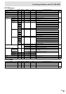
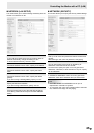
Initialization/Functional Restriction Setting (FUNCTION) menu
Function
Command Direction
Parameter Reply Control/Response contents *
ALL RESET RSET W 0-1 0: ALL RESET 1, 1: ALL RESET 2 -
ADJUSTMENT LOCK ALCK WR 0-2 0-2 0: OFF B
OSD DISPLAY LOSD WR 0-1 0-1 0: ON, 1: OFF B
LED OFLD WR 0-1 0-1 0: ON, 1: OFF B
TEMPERATURE ALERT TALT WR 0-2 0-2 0: OFF, 1: OSD & LED, 2: LED B
STATUS ALERT SALT WR 0-2 0-2 0: OFF, 1: OSD & LED, 2: LED B
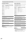
Others
Function
Command Direction
Parameter Reply Control/Response contents *
SCREEN SIZE (PC) WIDE WR 1-5 1-5 1: WIDE, 2: NORMAL, 3: Dot by Dot, 4: ZOOM1, 5: ZOOM2 B
SCREEN SIZE (AV) WIDE WR 1-5 1-5 1: WIDE, 2: ZOOM1, 3: ZOOM2, 4: NORMAL, 5: Dot by Dot B
VOLUME VOLM WR 0-31 0-31 B
MUTE MUTE WR 0-1 0-1 0: OFF, 1: ON -
INFORMATION MODEL INF1 R Value
A
SERIAL NO SRNO R Value
BRIGHT VLMP WR 0-31 0-31 Brightness B
TEMPERATURE SENSOR DSTA R 0 Internal temperature normal
A
1 Internal temperature abnormal (Standby mode)
2 Internal temperature abnormal (Temperature is normal now, but it was
abnormal during operation.)
3 Internal temperature abnormal (Brightness of the backlight decreases.)
4 Temperature sensor abnormal
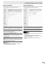
TEMPERATURE ACQUISITION ERRT R Value Temperature at temperature sensors 1 through 3 are returned in the
following forms:
[Sensor 1], [Sensor 2], [Sensor 3]
Indicates a temperature sensor abnormality when “126” is returned.
A
CAUSE OF LAST STANDBY MODE STCA W 0 Initialization
A
R 0 No detectable error has occurred
1 Standby mode by POWER button
2 Main power “OFF” by the main power switch
3 Standby mode by RS-232C or LAN
4 Waiting mode by No Signal (Incl: VESA DPMS/DMPM)
6 Standby mode by abnormal temperature
8 Standby mode by SCHEDULE setting