


EN-26
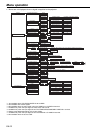
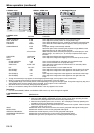
4. SIGNAL menu SIGNAL - USER menu 5. INFORMATION menu
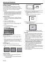
4. SIGNAL menu
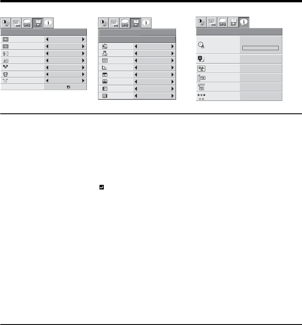
ITEM SETTING FUNCTION
HORIZ. POSITION 0-999 Use to adjust the horizontal position of the projected image.
VERT. POSITION 0-999 Use to adjust the vertical position of the projected image.
FINE SYNC. 0-31 Use to eliminate fl ickering or blur, if appears, viewing the projected image.
TRACKING 0-9999 Use to eliminate vertical wide stripes, if appears, viewing the projected
image.
COMPUTER INPUT AUTO The proper setting is automatically selected.
RGB Select this option when connecting the projector to high defi nition video
equipment having R, G, and B output terminals.
YC
BCR/YPBPR Select this option when connecting the projector to a DVD player or other
device having Y, C
B, and CR (or Y, PB, and PR) component video output
terminals.
OVER SCAN 100%-90% Use to adjust the display area of projected image.
HOLD OFF / ON
Use to adjust the image when fl agging occurs near the top of the screen.
USER
CLAMP POSITION 1-255 Use to correct solid white or solid black in the projected image.
CLAMP WIDTH 1-63 Use to correct solid black in the projected image.
VERT.SYNC AUTO / OFF Use to adjust the image when its motion doesn’t run smoothly. Select
AUTO for normal use.
LPF ON / OFF Use to select whether or not to enable the LPF.
SHUTTER(U) 0-20 Use to adjust the image when noise appears on the top part of the image.
SHUTTER(L) 0-20 Use to adjust the image when noise appears on the bottom part of the
image.
SHUTTER(LS) 0-20 Use to adjust the image when noise appears on the left half of the image.
SHUTTER(RS) 0-20 Use to adjust the image when noise appears on the right half of the
image.
• Though horizontal strips may appear on the enlarged projected image, such symptom is not a malfunction.
• When you change the horizontal or vertical position to a large extent, noise may appear.
• The adjustable range of the vertical position varies depending on the type of the input signal. Though the image may stay in the
same position even when the setting value is changed, such symptom is not a malfunction.
• SHUTTER will not work correctly during keystone adjustment.
• When you increase the setting value of OVER SCAN, noise may appear on the screen.
Important:
• You can set the IMAGE, SIGNAL, and SIGNAL-USER menus only when the signal is supplied.
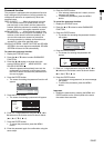
5. INFORMATION menu
ITEM DESCRIPTION
LAMP TIME (LOW) This item shows a lamp operating time (hour) calculated based on that LAMP MODE is LOW.
• When the LAMP MODE is STANDARD, this item shows a longer lamp operating time than
the actual time. (See page 36 for the interval of lamp replacement.)
• When the lamp operating time is 0 to 10 hours, "0H" is displayed. The lamp operating time
exceeding 10 hours is indicated by the actual hours.
• When the lamp operating time reaches 3750 hours, the bar turns to yellow. When it reaches
4750 hours, the bar turns to red.
INPUT Indicates the name of the terminal to which the currently projected video signal is being input.
RESOLUTION Indicates the resolution of the currently projected video signal.
VERTICAL FREQUENCY Indicates the vertical frequency of the currently projected video signal.
HORIZONTAL FREQUENCY Indicates the horizontal frequency of the currently projected video signal.
SYNC. TYPE Indicates the type of the sync signal for the currently projected video signal.
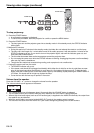
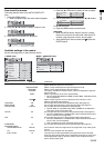
R G B
R G B
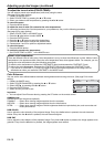
SIGNAL
HORIZ. POSITION 0
VERT.POSITION 0
TRACKING 0
COMPUTER
INPUT
RGB
FINE SYNC. 0
USER
opt.
OK
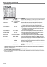
OFF
HOLD
100%
OVER SCAN
CLAMP
POSITION
USER
1
CLAMP WIDTH 1
LPF OFF
SHUTTER(U) 0
SHUTTER(L) 0
VERT. SYNC AUTO
?
SHUTTER(LS) 0
SHUTTER(RS) 0
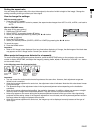
SIGNAL
opt.
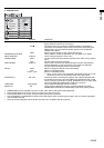
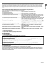
INFORMATION
opt.
LAMP TIME (LOW)
INPUT
RESOLUTION
VERTICAL
FREQUENCY
HORIZONTAL
FREQUENCY
SYNC. TYPE 5wire
60.02 KHz
75.04 Hz
1024x768
COMPUTER2
0 H
RG
HV
B
Menu operation (continued)