


EN-42
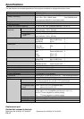
Specifi cations
The specifi cations and outside appearance of the projector are subject to change without prior notice.
*1
: Wireless LAN unit isn’t packaged together with the projector.
Replacement part
(Option/Not included in the box)
Spare lamp (for XL650U): VLT-XL650LP Spare lamp (for XL550U): VLT-XL550LP
Type
Model
Display Technology
Projection lens
Light-source lamp
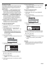
Image size (Projection distance)
Maximum
resolution
Computer signal
Video signal
Component
signal
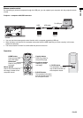
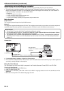
Computer/Component video input
Video input
Audio input
Monitor output
Audio output
Speaker
Control terminal/Others
Operating temperatures
Rated voltage
Power consumption
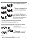
Dimensions
Weight
Others
S-video input
Video input
Component video
input
Analog input
Digital input (DVI)
Audio input
DC OUT
LCD projector
XL650U / XL550U
0.8-inch LCD panel: 3 pieces (for R,G,B)
Pixel: 1024 x 768 = 786432 pixels Total 2359296 pixels
Active pixel rate: 99.99% or more (each panel)
F 1.7 - 1.9 f= 24 - 29 mm
261 W (XL650U) / 200 W (XL550U)
40” min. to 300” max. (Projection distance 1.2 to 9.1 m)
Maximum resolution: 1600 x 1200 dots (Analog)/compressed
Panel resolution: 1024 x 768 dots
NTSC/PAL/SECAM/4.43NTSC/PAL-M/PAL-N/PAL-60
480i, 480p, 576i, 576p, 720p, 1080i
Panel resolution: 1024 x 768 dots
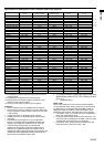
[Signal type] [Terminal type] [Line]
Analog RGB Mini D-SUB 15-pin 2
Digital RGB DVI-D 1
[Signal type] [Terminal type] [Line]
Video input RCA 1
S-Video input S 1
[Signal type] [Terminal type] [Line]
RGB Stereo mini jack (ø3.5) 2
Video RCA (L, R) 1
S-video RCA (L, R) 1
[Signal type] [Terminal type] [Line]
Analog RGB Mini D-SUB 15-pin 1
[Signal type] [Terminal type] [Line]
RGB/Video/S-video Stereo mini jack (ø3.5) 1
3 W Mono Round type ø4.5 cm
x
1
RS-232C (D-SUB 9-pin), USB terminal, LAN terminal (RJ-45)
+41°F (+5°C) to +95°F (+35°C)
AC100 - 240 V, 50/60 Hz
3.9 A (XL650U) / 2.9 A (XL550U)
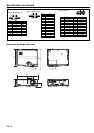
333 mm (W) x 113 mm (H) x 272 mm (D) * Not including protrusion.
4.7 kg (XL650U)/4.5 kg (XL550U)
Luminance signal: Vp-p=1.0 V 75 Ω (negative sync)
Chrominance signals: Vp-p=0.286 V 75 Ω (burst signal)
Vp-p=1.0 V 75 Ω (negative sync)
YC
B
C
R
: Vp-p=1.0 V 75 Ω (Y) (negative sync)
Vp-p=0.7 V 75 Ω (C
B
, C
R
)
RGB: Vp-p=0.7 V 75 Ω (negative sync)
YC
B
C
R
: Vp-p=1.0 V (Y) (negative sync) Vp-p=0.7 V (C
B
, C
R
)
HD/CS: TTL-level (negative or positive polarity)
VD: TTL-level (negative or positive polarity)
DVI-D interface (TMDS single link) with HDCP
350 mVrms, 10 kΩ or more
5 V 1.5 A (max) (For wireless LAN unit
*1
)