


9
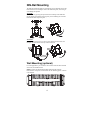
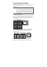
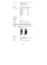
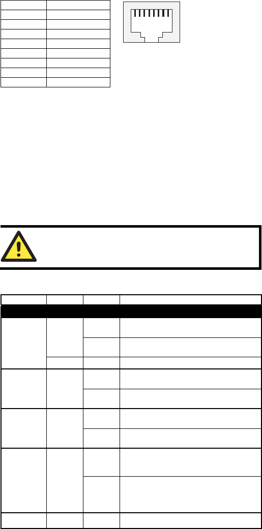
MDI/MDI-X Port Pinouts
Pin Signal
1 TRD(0)+
2 TRD(0)-
3 TRD(1)+
4 TRD(2)+
5 TRD(2)-
6 TRD(1)-
7 TRD(3)+
8 TRD(3)-
1
8
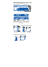
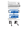
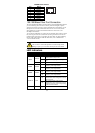
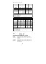
100/1000Base Fiber Port Connection
The concept behind the duplex port and cable is quite straightforward. Suppose
you are connecting devices I and II. Contrary to electrical signals, optical
signals do not require a circuit in order to transmit data. Consequently, one of
the optical lines is used to transmit data from device I to device II, and the
other optical line is used to transmit data from device II to device I, for
full-duplex transmission.
All you need to remember is to connect the Tx (transmit) port of device I to the
Rx (receive) port of device II, and the Rx (receive) port of device I to the Tx
(transmit) port of device II. If you make your own cable, we suggest labeling
the two sides of the same line with the same letter (A-to-A and B-to-B or
A1-to-A2 and B1-to-B2).
ATTENTION
This is a Class 1 Laser/LED product. To avoid causing serious
damage to your eyes, do not stare directly into the Laser Beam.
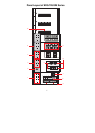
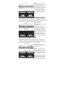
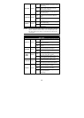
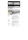
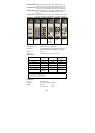
LED Indicators
LED Color State Description
System LEDs
On
System has passed self-diagnosis test on
boot-up and is ready to run.
GREEN
Blinking
System is undergoing the self-diagnosis
test.
STAT
RED On System failed self-diagnosis on boot-up.
On
Power is being supplied to the main
module’s power input PWR1.
PWR1 AMBER
Off
Power is not being supplied to the main
module’s power input PWR1.
On
Power is being supplied to the main
module’s power input PWR2.
PWR2 AMBER
Off
Power is not being supplied to the main
module’s power input PWR2.
On
The corresponding PORT alarm is
enabled and a user-configured event has
been triggered.
FAULT RED
Off
The corresponding PORT alarm is
enabled and a user-configured event has
not been triggered, or the corresponding
PORT alarm is disabled.