


8
Communication Connections
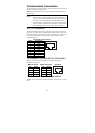
The pinout and cable wiring diagrams in this section show how the ports on the
EDS-728/828 connect to other devices:
Pinouts are diagrams that indicate the type of signal passing through each of
the port’s pins.
NOTE
1. The pin numbers for male DB9 and DB25 connectors, and hole
numbers for female DB9 and DB25 connectors are labeled on the
connector. However, the numbers are typically quite small, so you
may need to use a magnifying glass to see the numbers clearly.
2. The pin numbers for both 8-pin and 10-pin RJ45 connectors (and
ports) are typically not labeled on the connector (or port). Refer to
the Pinout diagram below to see how RJ45 pins are numbered.
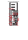
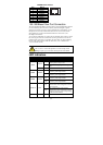
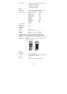
RS-232 Connection
The EDS-728/828 has one RS-232 (10-pin RJ45) console port, located on the
front panel. Use either an RJ45-to-DB9 or RJ45-to-DB25 cable to connect the
Moxa EDS-728/828’s console port to your PC’s COM port. You may then use
a console terminal program to access the Moxa EDS-728/828’s console
configuration utility.
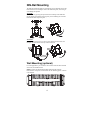
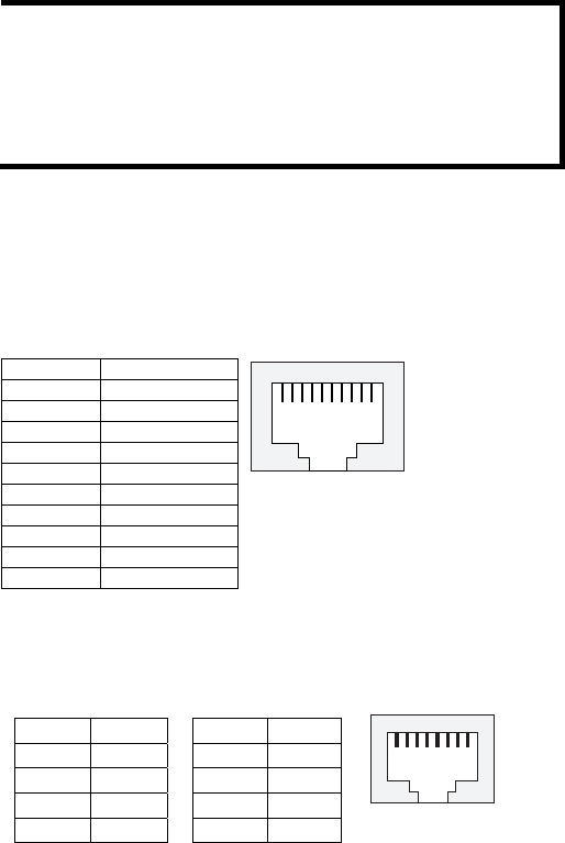
10-pin RJ45 Console Pinouts
10-Pin Description
1 ------
2 DSR
3 ------
4 GND
5 TxD
6 RxD
7 GND
8 ------
9 DTR
10 ------
110
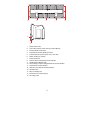
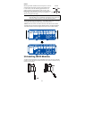
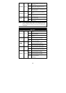
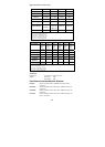
10/100BaseT(X) Ethernet Port Connection
Below we show pinouts for both MDI (NIC-type) ports and MDI-X
(HUB/Switch-type) ports.
MDI Port Pinouts MDI-X Port Pinouts 8-pin RJ45
Pin Signal Pin Signal
1 Tx+ 1 Rx+
2 Tx- 2 Rx-
3 Rx+ 3 Tx+
6 Rx- 6 Tx-
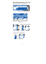
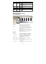
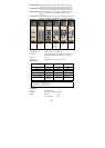
1000BaseT Ethernet Port Connection
1000BaseT data is transmitted on differential TRD+/- signal pairs over copper
wires.
1
8