


2-12
MS-9821 Mainboard
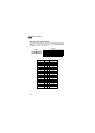
PIN SIGNAL DESCRIPTION
1 HD_LED + Hard disk LED pull-up
2 FP PWR/SLP MSG LED pull-up
3 HD_LED - Hard disk active LED
4 FP PWR/SLP MSG LED pull-up
5 RST_SW - Reset Switch low reference pull-down to GND
6 PWR_SW + Power Switch high reference pull-up
7 RST_SW + Reset Switch high reference pull-up
8 PWR_SW - Power Switch low reference pull-down to GND
9 RSVD_DNU Reserved. Do not use.
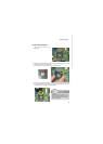
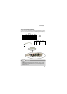
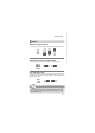
JFP1 Pin Definition
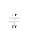
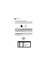
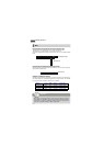
Front Panel Connector: JFP1
The mainboard provides one front panel connector for electrical connection to the
front panel switches and LEDs. The JFP1 is compliant with Intel
®
Front Panel I/O
Connectivity Design Guide.
1
2
910
JFP1
HDD
LED
Reset
Switch
Power
LED
Power
Switch
+
+
+
-
-
-
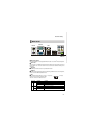
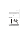
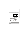
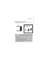
Fan Power Connectors: CPUFAN1, SYSFAN1
The fan power connectors support system cooling fan with +12V. When connecting
the wire to the connectors, always note that the red wire is the positive and should
be connected to the +12V; the black wire is Ground and should be connected to GND.
If the mainboard has a System Hardware Monitor chipset onboard, you must use a
specially designed fan with speed sensor to take advantage of the CPU fan control.
Important
Please refer to the recommended CPU fans at Intel
®
official website or consult
the vendors for proper CPU cooling fan.
SYSFAN1
SENSOR
+12V
GND
CPUFAN1
SENSOR
+12V
GND
CONTROL