


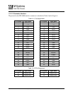
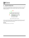


3. INTERFACE CONNECTORS
The IDE 4000 has a 2-mm pitch interface connector located on the rear panel. It accesses the DC
power source and the IDE bus through a non-shielded 44-pin flat cable. Figure 6 provides an
example of a connector that can be used to interface with this connector, but any compatible
connectors may be used.
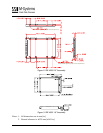
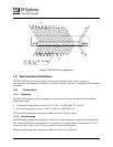
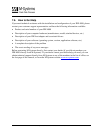
Figure 6: IDE 4000 Interface Connector
In order to prevent damage to the disk by connecting the cable with a 180º rotation, ensure that
the special plastic key at pin 20 mating connector is blocked, as shown in Figure 6. This key
should be ordered from the connector manufacturer.
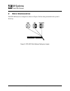
IDE Cable
The cable length should not exceed 18 inches.
14 Product Specification and User Manual IDE 4000 Flash Disk 34-PS-0304-00 Rev. 2.1