


Setup
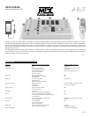
Input Level Adjustments (1) - The Input Level Adjustments should all be set to the centre position to start with. If one source is louder than the other sources, turn
both the Left and Right Input Level Adjustments for that source counterclockwise, reducing the input level to match the volume level of the other sources. If one
source is lower than the others, turn both the Left and Right Input Level Adjustments for that source clockwise, increasing the input level to match the volume level
of the other sources.
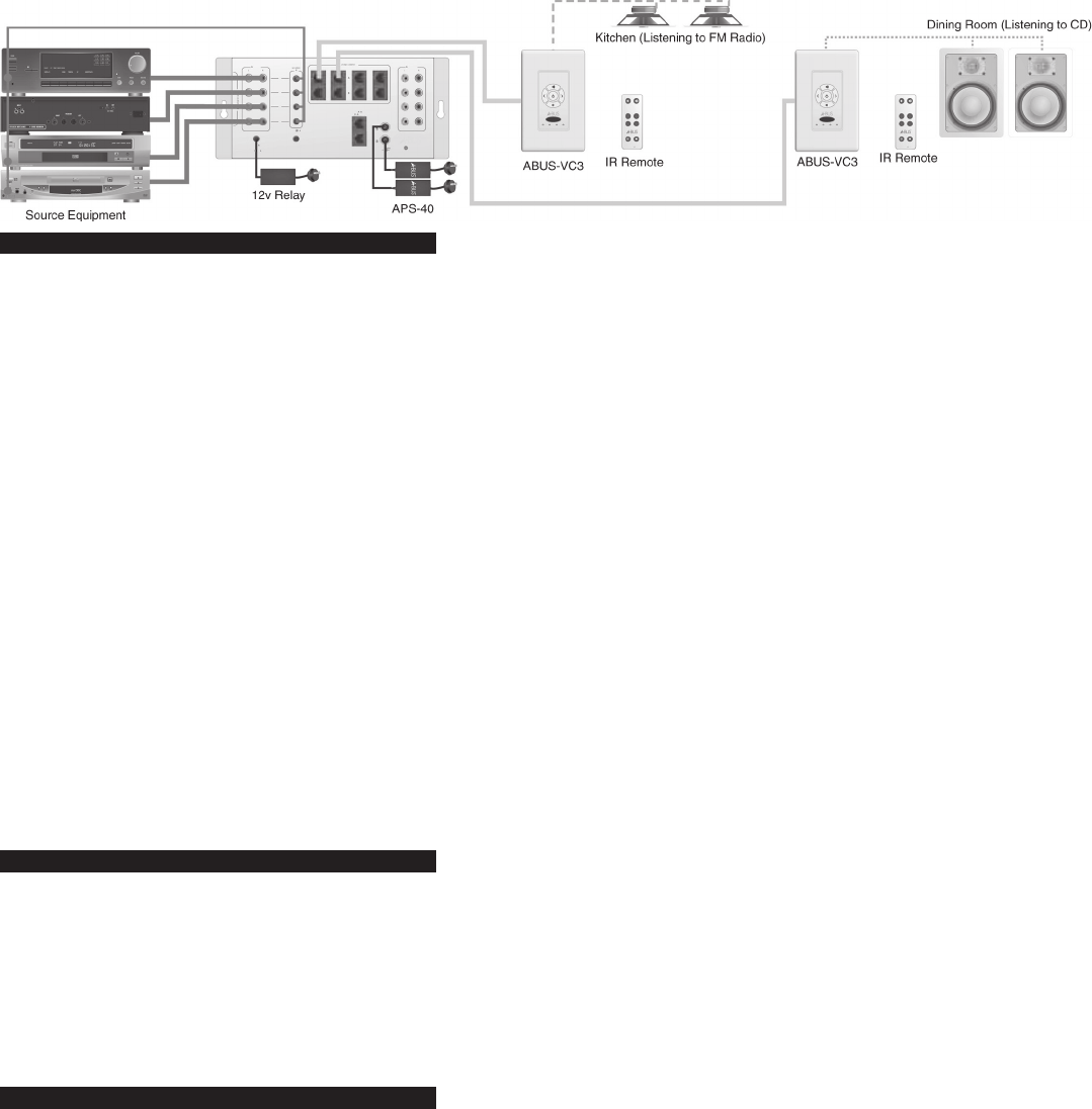
Trigger Output (3) - The Trigger Output may be used to activate a relay or other device that responds to a steady-state 12 volt trigger signal. This output may be used
to power a Power Strip, which may be used to power the source components. When the System Off command is pressed, the 12 Volt Trigger Output will be turned
off. Source components that are plugged into a trigger-controlled power strip will be switched off. Care should be taken to ensure that components will not lose their
memories (clocks, etc. or presets) after long periods of non-use.
Infrared (IR) Emitter Ports (5) (7) - There are 5 emitter ports, 4 are routed ports. The routed outputs will only emit commands from the zone that has selected that
source. This will allow more than one source device with the same code set to be used. If this is the case, light-blocking emitter caps should be used to prevent
infrared commands from straying into the infrared receivers of adjacent components. The common emitter port will generate all commands from any zone with infra
-
red capability. Some components have an IR IN socket on the back, it is recommended that this direct connection be used. CAUTION: Do not confuse a data bus
connection with an infrared port.
TIP: 1. Finding the Infrared receiver location in some components can be difficult. To find the right place, place a large card with a hole the size of a folder punch hole
in it over the front of the component and while generating a command from the components remote control handset move the card around until the unit responds to
the command.
2. In situations where the unit is not responding to the commands from the emitter or if the response is erratic the signal level may be too high. If the operation im
-
proves when the emitter is held away from the component a filter will be required such as some exposed camera film.
3. Some source components may not respond to repeated infrared commands. This is rare and may require a change in component.
System Indicator (4) - The green power light indicates when the system is turned on. The system is activated when the hub receives a source-select command from
any zone. Once a command has been received by the Hub to activate, a 12 volt signal will be available at the Trigger Output (3). Other zones may be activated at
any time. Individual volume control modules may require activation separately before sound can be heard. Regardless, of which Volume Control Modules are on or
off, the 12 volt trigger will remain active until a System Off command is sent to the Hub.
Infrared Talkback (6) - The Red Talkback indicator flashes when an Infrared data command is passing through the hub.
Mains Power (10) - The two red power lights indicated when the power supplies connected to bank A or bank B are active. These indicators do not indicate the
system is active (see System Indicator [4]).
System Design
The ABUS-HUB4X8 Multi-Source Multi-Zone Hub is compatible with any ABUS Volume Control Module; however, some Volume Control Modules do not have the
capability to control the ABUS-HUB4X8 Multi-Source Mulit-Zone Hub directly from keypad buttons. We recommend using only Volume Control Modules with IR
receivers built in, so that you will be able to control the ABUS-HUB4X8 Multi-Source Multi-Zone Hub by pointing a ABUS IR Remote at the Volume Control Module,
which will repeat the IR commands to the ABUS-HUB4X8.
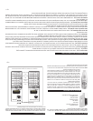
ABUS is a very flexible system, it allows for many variations not normally possible in traditional multi-room systems. For instance; it is possible to mix multi-source
hubs with single source hubs. There are many reasons you may want to do this, the most common reason is because in open plan houses you may have intercon
-
necting areas which are acoustically the same (family rooms, dining rooms and kitchens). So if you change the source in one area the other rooms can track the
same source. Another example is bedrooms with bathrooms. In the master bedroom, the full-function Volume Control Module would normally be used; however,
in the bathroom a less-expensive volume control module may be all that is needed. The Multi-Source Multi-Zone Hub has a second output port (the second bank
requires a separate power supply) in each zone to cater for this requirement. If additional areas are required, the second output port may be connected to a separate
4-room hub to expand that zone.
Operation
The ABUS-HUB4X8 Multi-Source Multi-Zone Hub is controlled by ABUS Infrared (IR) commands. There are four audio inputs. When the hub receivers a command
for any one of the four inputs in any zone, the hub will switch on. This will be indicated by the green power indicator. The 12 volt trigger will also activate. If source
components are activated by a power strip switched by the trigger, they will also activate. Each zone must have one power module with a keypad that includes but-
tons with ABUS functions (inputs 1-4 or Input Up/Down, Room Off and System Off commands). Alternatively, any Volume Control Module containing an IR receiver
may be used in conjunction with an ABUS remote that has these IR commands built-in. Volume Control Modules without Room On/Off switches will activate when any
Zone is turned on. Other modules with individual ON/OFF capability require either an on command or a volume Up/Down command to activate the module. These
units will reset to a low volume level the next time the system is turned on. The ABUS OFF command will turn off the Volume Control Module only. To turn the whole
system off, the SYSTEM OFF command must be used.
Infrared Repeater - Volume Control Modules that include infrared receivers will pass most infrared commands without difficulty. They will repeat standard 38 kHz
commands and 56 kHz commands which are often used in satellite receivers. Care should be taken to ensure the emitters are properly placed over the receiver on
the front of the component.
Infrared Range - The operating range of you remote control will vary according to the light conditions in the room, the quality of the IR remote (and battery condi
-
tion) and the system design in the components. In ideal conditions in areas with low light the range should be up to 20M (70ft.), however, in areas of high sunlight
or lighting such as low-voltage lighting which can emit light in the infrared frequency range the operating range can be substantially less. In direct sunlight the range
will go down to 5M (15ft.). Care should be taken when planning your ABUS system installation to locate the Volume Control Modules in a position away from direct
light and in a position convenient to the users to point the IR remote control to the receiver in the module.
Note: Remote controls are not RF devices. The commands are sent by line-of-sight and will not go around corners or through furniture or curtains.
Page 3
Page 4