


66
MultiModemBA User Guide
7.1 Introduction
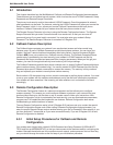
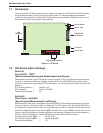
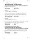
There are several DIP-Switch options on the modem’s printed circuit (PC) board. The DIP-Switches
are accessible through a cut-out on the side of the modem. This chapter explains the modem’s
printed-circuit board options. Sixteen DIP-Switch settings and the modem's speaker volume control
are explained in detail, including all default settings.
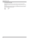
OPEN
13 14 15 16
OPEN
123456789101112
LED
Indicators
16-position DIP-switch
Phone Jack
Line Jack
RS-232/V.24
Connector
Power Jack
Power Switch
Figure 7-1. PC Board
7.2 DIP-Switch Option Settings
Switch #1
Forced DTR -- "DTR"
(Asynchronous/Synchronous Mode/Leased Line/Dial-Up)
The modem must have a high DTR signal in order to operate. DTR is provided to the modem by the
terminal or computer to which it is attached, through pin 20 of the RS-232C/V.24 interface. If your
terminal or computer is not providing DTR to the modem, you can force the DTR signal high with DIP-
Switch #1.
DTR function normally = Switch #1 UP
DTR forced On = Switch #1 DOWN
Factory Default Setting = UP
Switch #2
Flow Control - &E4/&E5
(Asynchronous Mode/Leased Line/Dial-Up)
With Hardware Flow Control, the modem uses its RS-232C/V.24 interface to control the flow of data
from the computer or terminal to which it is attached. The CTS signal on Pin 5 of the RS-232C/V.24
is brought low to stop the flow of data, and is brought high to restart it. Place DIP-Switch #2 in the UP
position to enable Hardware Flow Control (
&E4
). Xon/Xoff Flow Control (
&E5
) is another flow control
method. Xon/Xoff characters in the data dictate the start and stop of data flow from the computer or
terminal. Place DIP-Switch #2 in the DOWN position to select Xon/Xoff Flow Control.
Hardware Flow Control (
&E4
) = Switch #2 UP
Xon/Xoff Flow Control (&E5) = Switch #2 DOWN
Factory Default Setting = UP