


10
MultiFRAD 3000-Series User Guide
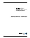
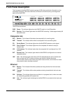
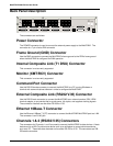
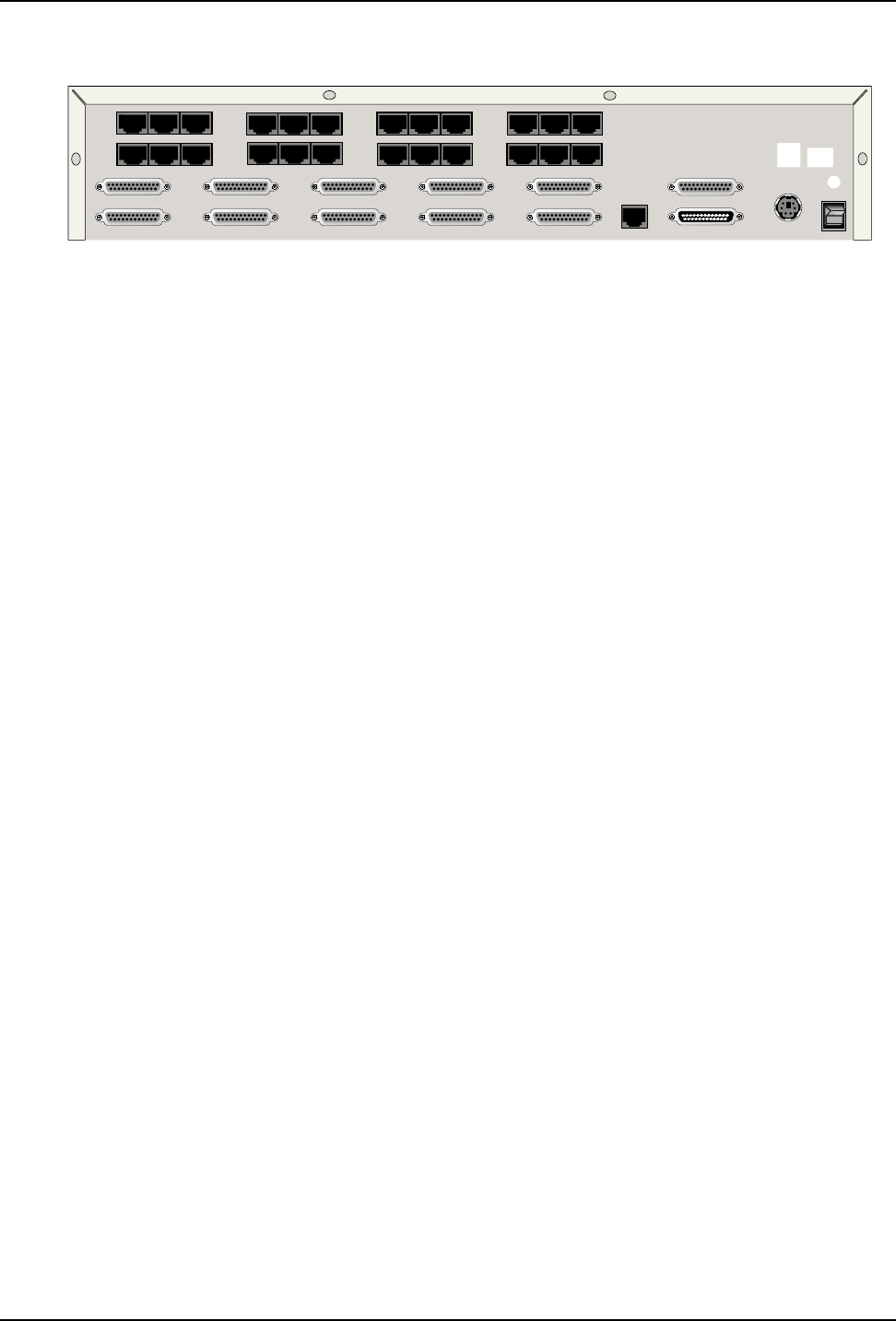
Back Panel Description
E&M FXO FXS E&M FXO FXS E&M FXO FXS E&M FXO FXS
VOICE/
FAX
CHANNEL
8
VOICE/
FAX
CHANNEL
4
VOICE/
FAX
CHANNEL
7
VOICE/
FAX
CHANNEL
3
VOICE/
FAX
CHANNEL
6
VOICE/
FAX
CHANNEL
2
VOICE/
FAX
CHANNEL
5
VOICE/
FAX
CHANNEL
1
CHANNEL 10
CHANNEL 9
CHANNEL 8
CHANNEL 7
CHANNEL 6
CHANNEL 5
CHANNEL 4
CHANNEL 3
CHANNEL 2 (RS232/V.35)
CHANNEL 1 (RS232/V.35)
10BASET
ETHERNET
COMMAND PORT
EXT. COMPOSITE LINK (RS232/V.35)
POWER
I
O
GND
T1 DSU
MONITOR
XMT RCV
INTERNAL
COMPOSITE
LINK
The connectors are as follows:
Power Connector
The POWER connector is used to connect the external power supply to the MultiFRAD. The
connector is a 7-pin circular DIN connector.
Frame Ground (GND) Connector
Use the GND connector to connect the MultiFRAD’s frame ground to the PBX’s frame ground
when the MultiFRAD is configured for E&M operation.
Internal Composite Link (T1 DSU) Connector
This connector is not currently supported.
Monitor (XMT/RCV) Connector
This connector is not currently supported.
Command Port Connector
Use this DB-25 female connector to connect the MultiFRAD to a PC running Windows or
terminal with communications software in order to configure the MultiFRAD.
External Composite Link (RS232/V.35) Connector
Use this DB-25 male connector to connect the MultiFRAD to an external modem, DSU, ISDN
terminal adapter, or any device that is synchronous, full duplex, and supplies clocking signals.
The connection interface can be either RS-232 or V.35.
Ethernet 10Base-T Connector
Use the Ethernet 10Base-T (UTP) connector to connect the MultiFRAD MultiFRAD port to a LAN.
The connector is an RJ-45 jack.
Channels 1 & 2 (RS232/V.35) Connectors
The connectors for Channels 1 and 2 are used to connect the MultiFRAD to data devices. A data
device can be a HDLC synchronous device such as a multiplexer or an asynchronous device
such as a PC. These two data channels can be either RS-232 or V.35. The connectors are DB-
25 female connectors.