


ISI Quick Start Guide
4
4. Carefully remove the ISI Card from its antistatic bag, handling it only by the
mounting bracket and edges. Do not touch the gold-plated connectors along the
bottom edge. (You may want to save packaging for possible future use.)
5. Locate the unused PCI slot you will be using for your ISI Card and remove the
slot cover according to instructions in your computer's documentation.
6. Install the ISI Card into the selected expansion slot in the same manner as any
other add-on card, as instructed in your computer’s documentation.
7. Fasten the retaining bracket to the computer chassis and replace cover on the
computer.
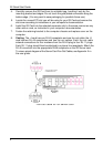
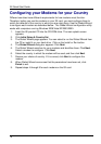
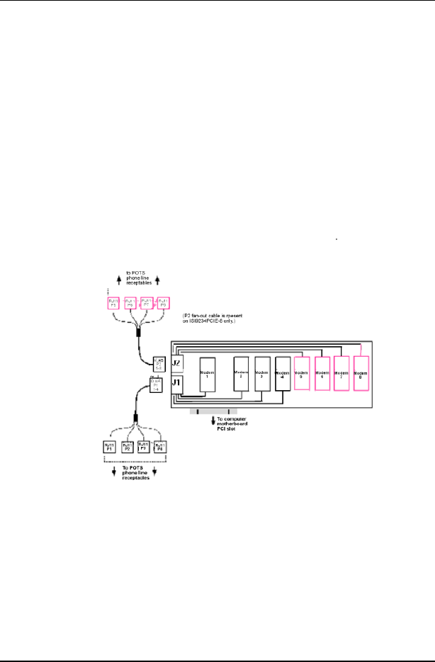
8. Cabling. The -4 card has one RJ-45 receptacle and one fan-out cable; the -8
card has two RJ-45 receptacles and two fan-out cables. Each fan-out cable
extends connections for four modems from the RJ-45 plug to four RJ-11 plugs.
Each RJ-11 plug should then be attached to a phone line receptacle. Attach the
RJ-45 connector into the appropriate RJ45 receptacle on the ISI Server card.
To view a pinout diagram of the Server Card Fan-Out Cables, see Appendix A in
the user guide.
Fan-Out Cable for ISI Server Card