Chapter 3 – Voice Commands
Multi-Tech Systems, Inc. AT Commands Reference Guide (S000273G) 33
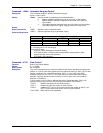
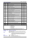
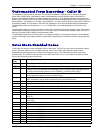
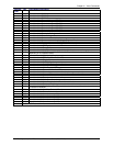
Table of +VLS Command Options
Label Primitives Description +VTX +VRX +VSP=1
0 None DCE on-hook. Local phone connected to the line.
1 T DCE off-hook. DCE connected to the line. Local phone provided with
power to detect hook condition.
X X
2 L DCE on-hook. Local phone connected to the DCE. X X
3 LT DCE off-hook. Local phone connected to the line.
DCE connected to the line.
X X
4 S Internal Speaker connected to the DCE. DCE on-hook.
Local phone connected to the line.
X
5 ST Internal Speaker connected to the line. DCE off-hook. DCE connecte
d
to the line. Local phone provided with power to detect hook condition.
X X
6 M Internal Microphone connected to the DCE. DCE on-hook.
Local phone connected to the line.
X
7 MST Internal Microphone and Internal Speaker connected to the line. DCE
off-hook. DCE connected to the line. Local phone provided with
power to detect hook condition.
X
8 S1 External Speaker connected to the DCE. DCE on-hook. Local phone
connected to the line.
X
9 S1T External Speaker connected to the line. DCE off-hook.
DCE connected to the line. Local phone provided with power to
detect hook condition.
X X
10 MS1T Internal microphone and External Speaker connected to the line. DCE
off-hook. DCE connected to the line.
Local phone provided with power to detect hook condition.
X
11 M1 External Microphone connected to the DCE. DCE on-hook.
Local phone connected to the line.
X
12 M1ST External Microphone and Internal Speaker connected to the line.
DCE off-hook. DCE connected to the line. Local phone provided with
power to detect hook condition.
X
13 M1S1T External Microphone and External Speaker connected to the line.
DCE off-hook. DCE connected to the line. Local phone provided with
power to detect hook condition.
X
14 H External Microphone and Speaker combination (handset or headset)
connected to the DCE. DCE on-hook.
Local phone connected to the line.
X X
15 HT External Microphone and Speaker combination (handset or headset)
connected to the line. DCE off-hook. DCE connected to the line. Local
phone provided with power to detect hook condition.
X X
16 MS MS Internal Microphone and Internal Speaker connected to DCE.
17 M1S MS1 Internal Microphone and External Speaker connected to DCE.
18 MS1 External Microphone and Internal Speaker connected to DCE.
19 M1S1 External Microphone and External Speaker connected to DCE.
Primitives (Column 2): L Local Phone.
T Telephone Line.
M Internal Microphone.
M1 External Microphone.
S Internal Speaker.
S1 External Speaker.
H External Microphone and Speaker combination (handset or headset).
Note: All label options in this table may not be supported by the product; see +VLS command
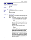
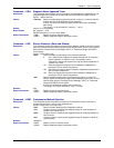
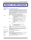
Command: +VRA Ringback Goes Away Timer
Description: This command sets the length of time the modem will wait between ringbacks during call
origination before the modem can assume that the remote station has gone off-hook.
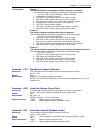
Syntax: +VRA=<interval>r r
Values: <interval> Decimal number (0-255) specifying the silence interval time in units of 0.10
second between the end of one ring interval and the start of the next ring
interval. A value of 0 forces the modem to report the OK result code
immediately after the first Ringback. Range is 0.1 to 25.5 seconds for
<interval> = 1 to 255.
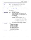
Default: Interval of 50 (5 seconds)
Report Commands: +VRA? Reports current of selected values.
+VRA=? Reports supported range of parameter values.


