


Chapter 2 – Mechanical Specifications
Multi-Tech Systems, Inc. SocketModem MT5600SMI Developer’s Guide 11
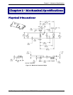
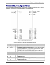
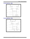
Parallel Pin Configurations
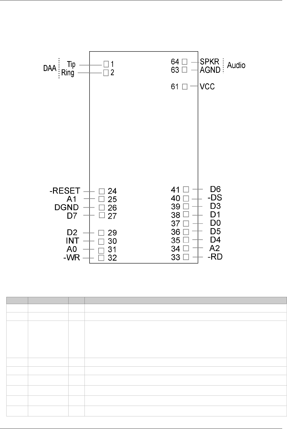
The parallel interface SocketModem uses a 22-pin interface to provide an on-board DAA with tip and ring
connections, audio circuit for call-progress monitoring, and parallel interface.
Figure 2–3. Parallel SocketModem Pins
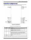
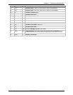
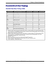
Pin Descriptions for a Parallel SocketModem Device
Pin # Signal Name I/O Description
1 Tip I/O
Telephone Line Interface – TIP
2 Ring I/O
Telephone Line Interface – RING
24 –RESET I
Modem Reset (CMOS input with weak pull-up). The active low –RESET input
resets the SocketModem logic and returns the AT command set to the original
factory default values or to "stored values" in NVRAM.
The modem is ready to accept commands within 6.5 seconds of power-on or
reset. Reset must be asserted for a minimum of 300 ns.
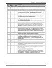
25 A1
Host Bus Address Line 1
26 DGND GND
Digital Ground
27 D7 O
Host Bus Data Line 7
29 D2 O
Host Bus Data Line 2
30 INT O
Host Bus Interrupt Line, Active High, Resets on Low
31 A0 I
Host Bus Address Line 0