


Chapter 4 – SocketModem Parallel Interface – A Programmer's Description
Multi-Tech Systems, Inc. SocketModem MT5600SMI Developer’s Guide 25
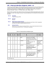
LSR – Line Status Register (Addr = 5)
This 8-bit register provides status information to the host concerning data transfer.
Bit 7 RX FIFO Error
In the 16450 mode, this bit is not used and is always 0.
In the FIFO mode, this bit is set if there are one or more characters in the RX FIFO with parity
error, framing error, or break indication detected. This bit is reset to a 0 when the host reads the
LSR and note of the above conditions exist in the RX FIFO.
Bit 6 Transmitter Empty (TEMT)
This bit is set to a 1 whenever the TX Buffer (THR) and equivalent of the Transmitter Shift
Register (TRS) are both empty. It is reset to a 0 whenever either the THR or the equivalent of the
TSR contains a character.
In the FIFO mode, this bit is set to a 1 whenever the TX FIFO and the equivalent of the TSR are
both empty
Bit 5 Transmitter Holding Register Empty (THRE) [TX Buffer Empty]
This bit, when set, indicates that the TX Buffer is empty and the modem can accept a new
character for transmission. In addition, this bit causes the modem to issue an interrupt to the host
when the Transmit Holding Register Empty Interrupt Enable bit (IIR1) is set to 1. The THRE bit is
set to a 1 when a character is transferred from the TX Buffer. The bit is reset to 0 when a byte is
written into the TX Buffer by the host.
In the FIFO mode, this bit is set when the TX FIFO is empty; it is cleared when at lease one byte
is in the TX FIFO.
Bit 4 Break Interrupt (BI)
This bit is set to a 1 whenever the received data input is a space (logic 0) for longer than two full
word lengths plus 3 bits. The BI is reset when the host reads the LSR.
Bit 3 Framing Error (FE)
This bit indicates that the received character did not have a valid stop bit. The FE bit is set to a 1
whenever the stop bit following the last data bit or parity bit is detected as a logic o (space). The
FE bit is reset to a 0 when the host reads the LSR.
In the FIFO mode, the error indication is associated with the particular character in the FIFO it
applies to. The FE bit set to a 1 when this character is loaded into the RX Buffer.
Bit 2 Parity Error (PE)
This bit indicates that the received data character in the RX Buffer does not have the correct
even or odd parity, as selected by the Even Parity Select bit (LCR4) and the Stick Parity bit
(LCR5). The PE bit is reset to a 0 when the host reads the LSR.
In the FIFO mode, the error indication is associated with the particular character in the FIFO it
applies to. The PE bit set to a 1 when this character is loaded into the RX Buffer.
Bit 1 Overrun Error (OE)
This bit is set to a 1 whenever received data is loaded into the RX Buffer before the host has
read the previous data from the RX Buffer. The OE is reset to a 0 when the host reads the LSR.
In the FIFO mode, if data continues to fill beyond the trigger level, an overrun condition will occur
only if the RX FIFO is full and the next character has been completely received.
Bit 0 Receiver Data Ready (DR)
This bit is set to a 1 whenever a complete incoming character has been received and transferred
into the RX Buffer. The DR bit is reset to a 0 when the host reads the RX Buffer.
In the FIFO mode, the DR bit is set when the number of received data bytes in the RX FIFO
equals or exceeds the trigger level specified in the FCR0-FCR1.