Chapter 4 – SocketModem Parallel Interface – A Programmer's Description
Multi-Tech Systems, Inc. SocketModem MT5600SMI Developer’s Guide 24
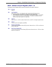
MCR – Modem Control Register (Addr = 4)
The Modem Control Register (MCR) controls the interface with modem or data set.
Bit 7-5 Not used
Always 0
Bit 4 Local Loopback
When this bit is set to a 1, the diagnostic mode is selected and the following occurs:
1. Data written to the Transmit Buffer is looped back to the Receiver Buffer.
2. The DTS (MCR0), RTS (MCR1), Out1 (MCR2), and Out2 (MCR3) modem control register
bits are internally connected to the DSR (MSR5), CTS (MSR4), RI (MSR6), and DCD
(MSR7) modem status register bits, respectively.
Bit 3 Output 2
When this bit is a 1, HINT is enabled. When this bit is a 0, HINT is in the high impedance state.
Bit 2 Output 1
This bit is used in local loopback (see MCR4).
Bit 1 Request to Send (RTS)
This bit controls the Request to Send (RTS) function. When this bit is a 1, RTS is on. When this
bit is a 0, RTS is off.
Bit 0 Data Terminal Ready (DTR)
This bit controls the Data Terminal Ready (DTR) function. When this bit is a 1, DTR is on. When
this bit is a 0, DTR is off.


