


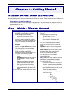

Chapter 2 – Getting Started
Multi-Tech Systems, Inc. MultiModem Wireless Modem with Ethernet Interface (S000375B) 10
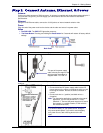
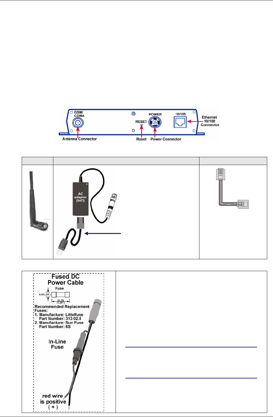
Step 2. Connect Antenna, Ethernet, & Power
Antenna
Connect a suitable antenna to SMA connector. An antenna is supplied with the bundled package ship kit. If
you purchase a single unit, you must supply your own antenna. See the User Guide for antenna/RF
specifications.
Ethernet
Using an RJ-45 Ethernet cable, connect the 10/100 jack to an internal network switch or hub.
Power
Plug one end of the power cord into the device and the other end onto a live power outlet.
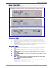
Notes
• The PWR LED. The PWR LED lights after power-up.
• The Reset Button. Pressing and holding the Reset button for 5 seconds will restore all factory default
settings.
Back Panel
Antenna Power Supply Cable Ethernet Cable
This part of the power supply
cable varies by the region of the
world to which the product is
shipped: NAM / EU / GB / IE
Note: Units shipped with the universal AC power supply are not suited for installation in hazardous
locations.
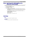
Fused DC Power Connection
• Connect the direct-DC power supply cable into the DC
power source on the vehicle or machine in which you are
mounting the modem. Be sure the GND connection is
correct.
• Connect red wire to + (positive) and black wire to –
(negative).
Note: For automotive application: according to the type of
application, you can use permanent “+” or key-
switched “+”. Connect the power supply to its source
(for example, in a mobile situation, to the vehicle’s
DC fuse/terminal block).
Warning: Do not connect your wireless modem directly
to a vehicle’s battery for your power source. Doing so
may cause power spikes. If you wish to use the battery
as a power source, add a filtering device to the DC
input.