


Appendix B – Wireless Antenna
Multi-Tech Systems, Inc. MultiModem Wireless Modem with Ethernet Interface (S000375B) 55
Appendix B – Wireless Antenna
The Antenna
The antenna sub-system and integration in the application is a major issue: Choice of antenna (type, length,
performances, thermal resistance, etc.) These elements could affect GSM performances such as sensitivity and
emitted power.
GSM, EDGE, and CDMA Antenna
The integrated modem antenna connector is a SMA connector. The SMA connector incorporates a 'Screw-on'
action in order to make the connection easier while providing an excellent RF performance. An additional
advantage is its small physical size, which is 50% of the standard MCX connector.
This type of connector is suitable for the standard ranges of flexible and semi-rigid cables. The characteristic
impedance of the MMCX coaxial connector is 50 ohm. The antenna manufacturer must guarantee that the
antenna will be working according to the radio characteristics presented in the table below.
GSM and E-GSM Radio Characteristics
GSM 850 E-GSM 900 GSM 1800 GSM 1900
Frequency RX
869 to 894 MHz 925 to 960 MHz 1805 to 1880 MHz 1930 to 1990 MHz
Frequency TX
824 to 849 MHz 880 to 915 MHz 1710 to 1785 MHz 1850 to 1910 MHz
RF Power Stand
2W at 12.5% duty cycle 2W at 12.5% duty cycle 1W at 12.5% duty cycle 1W at 12.5% duty cycle
Impedance 50 ohms
VSWR <2
Typical Radiated Gain 0 dBi on azimuth plane
CDMA Radio Characteristics
CDMA 800 CDMA 1900
Frequency RX
869 to 894 MHz 1930 to 1990 MHz
Frequency TX
824 to 849 MHz 1850 to 1910 MHz
Impedance
50 ohms
VSWR
<2
Typical Radiated Gain
0 dBi in at least one direction
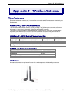
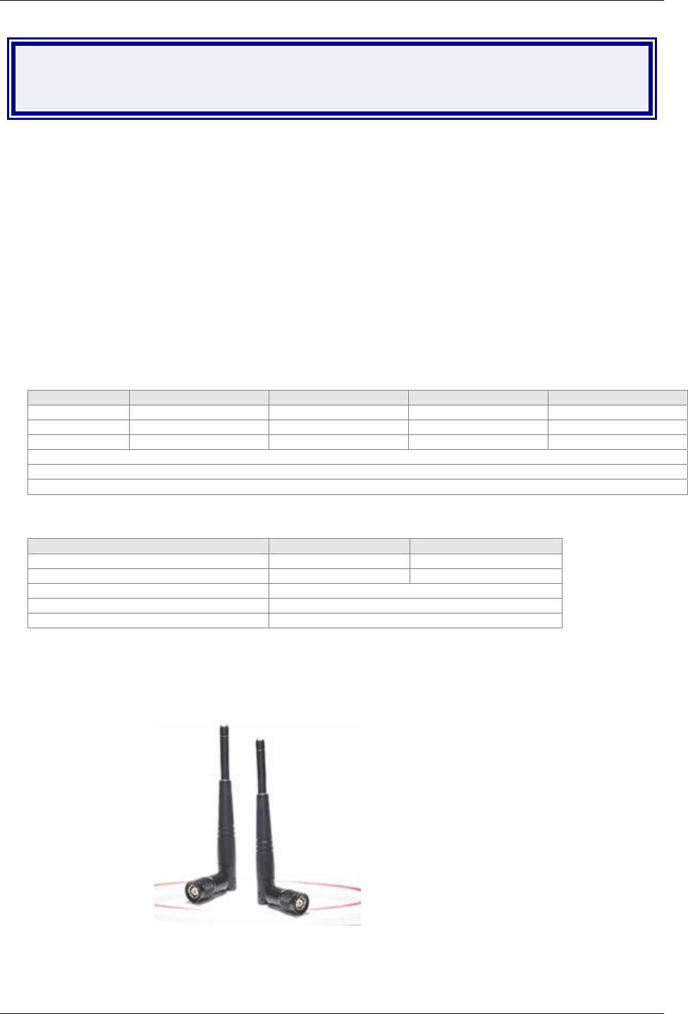
Antenna
An antenna that meets the requirements for use with the wireless product is included with your purchase.