


Section 78 00-02-0618
04-10-07 - 2 -
Installation Instructions
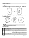
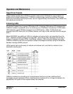
Configuration
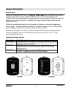
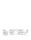
CANdrive modules are supplied with 5 circuit board links soldered in place. These wire links,
labeled L1 through L5, are located on the back side of the unit.
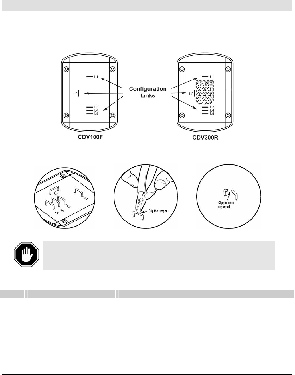
The links allow configuration of operating options by snipping the appropriate wire according to
the following configuration table.
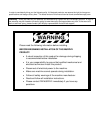
WARNING: The configuration links are one-time breakable and are
not replaceable. Care must therefore be taken to select the
correct options before cutting links.
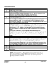
Configuration Table
Link Function Link Options
L1 CANbus 120 Ohm resistor Cut L1 to remove 120 Ohm terminating resistor.
Leave L2 intact for 12V operation L2 DC supply voltage
Cut L2 for 24V operation
Leave L3 and L4 intact for Murphy gages (see
compatibility table)
Cut L3 only for Datcon gages (see compatibility table)
L3
L4
Gage output options
Cut L4 only for VDO gages (see compatibility table)
Leave L5 intact for 0-7 bar gages L5 VDO pressure gage range
Cut L5 for 0-10 bar gages