


TYPICAL APPLICATIONS
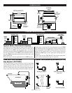
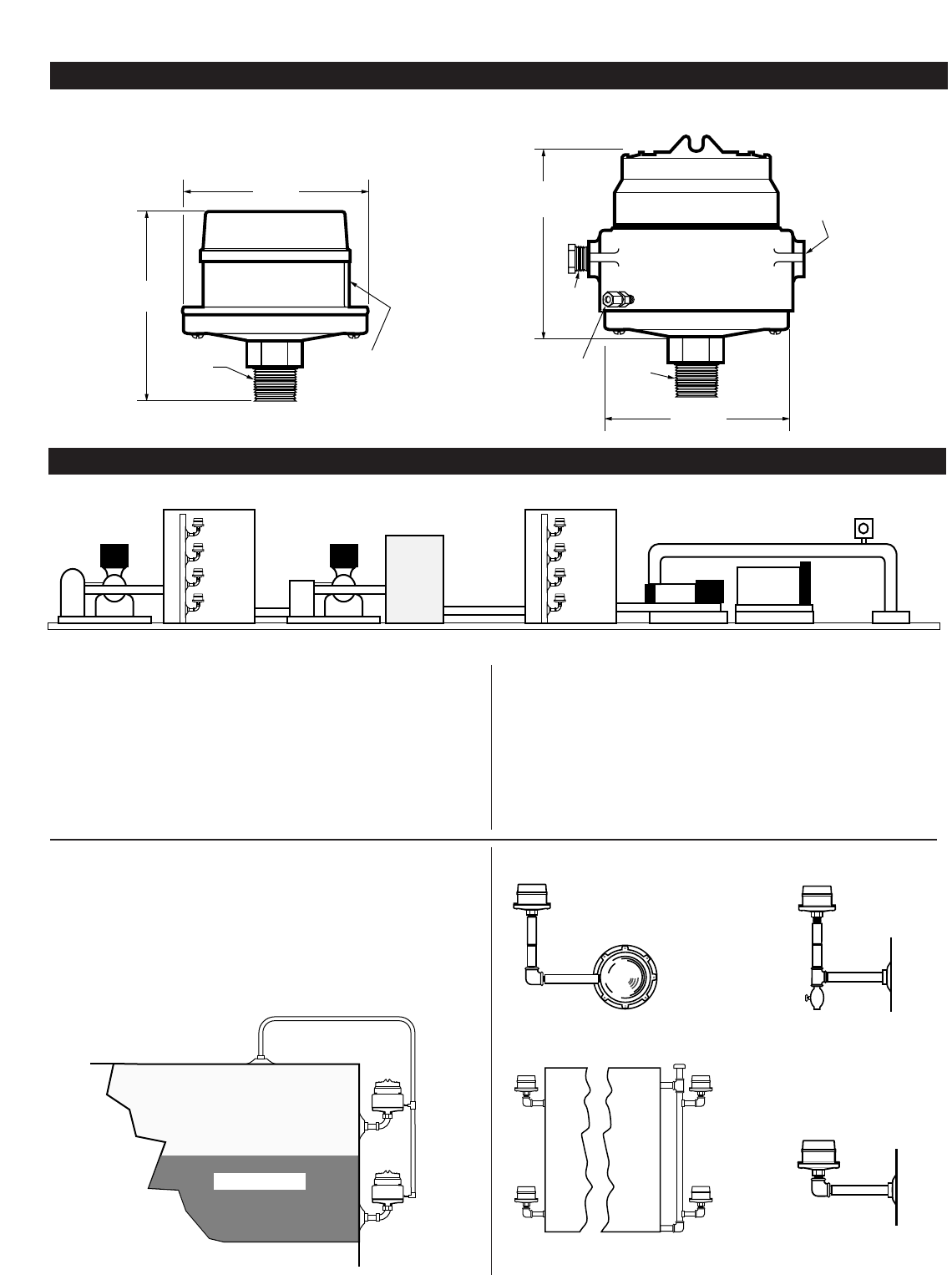
DIMENSIONS
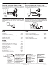
Typical Water Flood Control System
The diagram above displays eight DF Series switches installed on a
Raw Water tank and a Clear Water tank. When raw water rises to
predetermined level, DF#1 stops the supply pump. As tank level
falls below the predetermined level, DF#2 starts the supply pump. If
the tank level continues to fall, DF#3 initiates shutdown of the sup-
ply pump. DF#4 stops transfer pump before raw water tank is com-
pletely pumped out.
When clear water reaches the predetermined level, DF#5 stops the
transfer pump. As tank level falls to predetermined low level, DF#6
starts the transfer pump. If the tank level continues to fall due to the
failure of the filters section, DF#7 initiates shutdown of the transfer
pump. (DF755 located at this level will also operate backwash
equipment). DF#8 stops injection pump before tank pumps com-
pletely out.
An OPL Series pressure SWICHGAGE
®
stops injection pump when
pressure reaches predetermined high or low pressure.
Transfer
Pump
Supply
Pump
Raw Water Tank Clear Water Tank
Injection Pump
DF#1
DF#2
DF#3
DF#4
DF#5
DF#6
DF#7
DF#8
OPL Series
SWICHGAGE
®
Filter
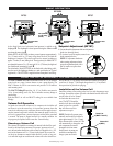
Tank with Low Pressure
Gas Blanket (DF755EX)
The DF755EX (below) is shown installed on a crude oil tank where
a low pressure gas blanket is used to prevent evaporation loss. It is
mounted directly to the side of the tank or on riser pipe 4 to 7 in.
(102 to 178 mm) below level to be controlled. Pump automatically
stops or starts when liquid reaches predetermined high or low level.
Fuel Tank
Gas Blanket
Gas Liquid
Typical Tank Mounting Methods (DF755)
Tank Wall Mounting With
Drain Cock
Bull Plug Installation
Directly
On Tank
Riser Pipe
Method
Tank Wall Mounting
DF755 and DF757
DF755EX
1 NPT
(standard)
6-5/32 in.
(156 mm)
5-1/2 in.
(140 mm)
1/2 NPT
For Electrical
Connection
7-21/32 in.
(194 mm)
5-5/8 in.
(143 mm)
1 NPT
(standard)
1/2 NPT
Plug
1/2 NPT
For Electrical
Connection
1/4 in. (6 mm)
Tube Fitting
(DF756 only)
DF-94063N page 2 of 4