


DF-94063N page 3 of 4
The MAC1 Volume Air Cell when attached to the DF755 can monitor
water levels on a sump. Activate alarms or start a pump directly. The
MAC1 Volume Air Cell is non-corrosive and provides 1/4-20 stainless
steel mounting studs.
The MACT1 Tubing Kit provides 4 ft. (1.2 m) flexible, non-corrosive
1/4 in. (6 mm) tubing (cut to fit). The kit includes necessary fittings to
attach tubing.
Both the MAC1 air cell and MACT1 tubing kit are available from
Murphy.
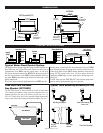
Volume Cell Operation
As liquid rises around the volume cell, it compresses air inside the cell
and forces it up in the sensor line. As air pressure increases due to the
water level continuing to rise, sufficient pressure will be applied to acti-
vate the internal snap-switch, which in turn starts the pump. As the liq-
uid level is pumped down, pressure decreases and the above procedure
is reversed. The pump is stopped and held in a standby condition. An
air purge may be required in the sensor line. Consult factory.
Choosing a Volume Cell
The volume cell should be constructed of material which will be unaf-
fected by the liquid being measured. For proper “pressure-to-level”
ratio, the minimum dimensions of the volume cell should be 6 in. (152
mm) inside diameter and 3 in. (76 mm) inside depth. The sensor line
can be of any diameter or material either flexible, or solid, as long as it
is of sufficient length to reach from the volume cell to the desired loca-
tion for the DF755. All fittings and connections should be air-tight to
avoid loss of “charge”. Tube lengths longer than 4 ft. (1.2 m) should
have provision for periodic air purging.
Installation of the Volume Cell
Install the volume cell according to the level you wish the pump to start
and stop. Secured the volume cell with a substantial bracket which will
not allow the cell to be “floated”
or tilted when the water level
rises. The DF755 should be
installed well above the highest
water level and in a position
that will allow access for
adjustment or repair.
NOTE: Periodically operate pump
manually until water level reaches a
point approximately 1/2 in. (13 mm)
below bottom of the volume cell. This
will automatically re-charge the unit
and compensate for normal
absorption of air into water.
Small electric air pumps are
available to automatically
charge system at all times.
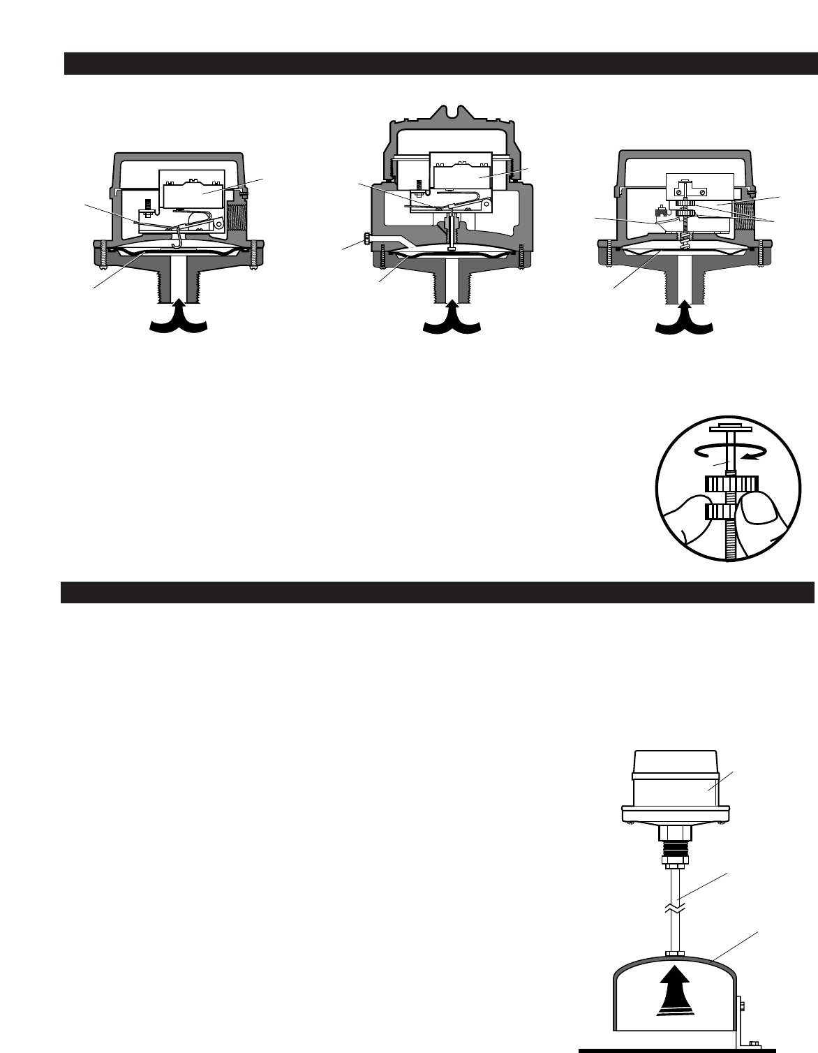
USING THE DF755 WITH MAC1 VOLUME CELL ACCESSORY
AIR
Sensor Line
(MACT1 Tube Kit)
DF755
Volume Cell
(MAC1)
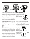
A
B
C
Hydrostatic Head
Pressure
Vent (DF755EX)
or Tube Fitting
(DF756)
B
C
A
Hydrostatic Head
Pressure
Hydrostatic Head
Pressure
B
D
A
C
As the liquid level rises, hydrostatic head pressure is applied to the
diaphragm
A. The diaphragm is forced upward forcing the actuator arm B
to activate the snap-switch C.
Models DF755 and DF755EX are factory set and operate at approximately
2 in. (51 mm) and 6 in. (152 mm) rising above the level at which the
diaphragm is mounted. The switch resets back to normal condition at
approx. 2 inches (51 mm) falling level. The trip point(s) for Model DF757
are adjustable between 2 in. (51 mm) and 110 in. (2794 mm) for high and
low (make/break) operation by knobs,
D.
For sealed tanks, model DF755EX can be fitted with a tube fitting to bal-
ance the top of the diaphragm chamber to a tank gas blanket (see Typical
Applications). The DF755EX is supplied with an atmospheric vent fitting.
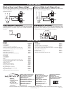
Setpoint Adjustment (DF757)
1. Locate threaded adjustment shaft and adjustment
knobs (see drawing above).
2. To increase low level setpoint, rotate lower
knob counterclockwise.
NOTE: If adjustment shaft turns
when rotating adjustment knobs,
grasp the adjustment shaft with a
pair of needle nose pliers–then
rotate knob.
DF755
DF755EX
DF757
BASIC OPERATION
Adjustment
Shaft