


If switch trip point needs to be adjusted, see page 4.
LLS Series Hook-up (all models)
To wire the LLS Series, use proper the electrical conduit.
1. A 3/4''-14 NPT inlet connection for conduit installation is provided
at the top end of the switch enclosure (see opposite page–
“Dimensions” for location).
NOTE: The plastic plug (supplied) is to protect the conduit inlet threads
and must be removed before wiring the unit.
2. Using a 3/16 in. hex wrench, unscrew the 4 hex-cap screws.
Now proceed to remove the square cover to reveal snap-switch(es).
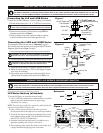
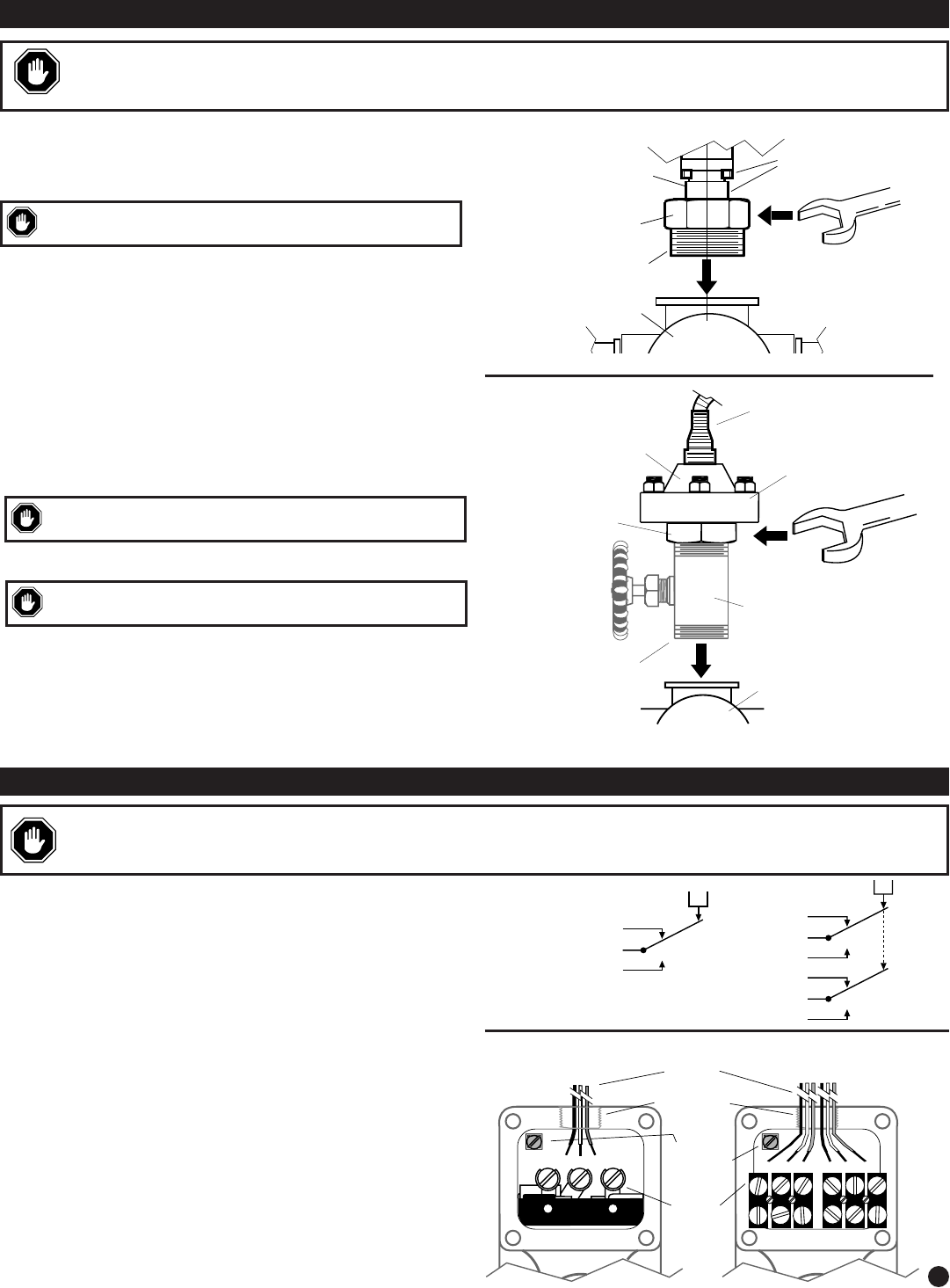
3. To wire the unit, refer to the typical wiring drawing (Figure 3) and
to the Schematic (shown at right). Wire the LLS Series switch(es)
with 60°/75°C (140°/167°F) insulated wire.
4. A terminal (inside the switch enclosure) is provided for case or
equipment grounding, refer to Figure 3 for location.
5. After completing wiring, replace the switch cover and make sure it
is tightly secured before applying power to the system.
3
WIRING THE LLS SERIES PRESSURE SWITCH
Provision for
Case Ground
N.O. N.C. COM.
Terminal
Block(s)
Customer
Wiring
NC NO C NC NO C
3/4 in.-14 NPT
Conduit Inlet
WARNING: PERFORM THE WIRING OPERATION WITH THE POWER SOURCE “OFF”. MAKE SURE VOLTAGE AND CURRENT REQUIRE-
MENTS ARE WITHIN THE LLS RATINGS. BEFORE WIRING THE UNIT DETERMINE VOLTAGE AND POLARITY FOR THE APPLICATION.
IF THE UNIT IS USED IN HAZARDOUS AREAS, MAKE THE AREA SAFE BEFORE REMOVING THE SNAP-SWITCH(ES) COVER.
Figure 3
SPDT
DPDT
NC
C
NO
P
NC
C
NO
P
NC
C
NO
Schematic
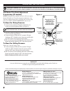
INSTALLING THE LLS SERIES PRESSURE SWITCH
Connecting the LLS and LLSB Series
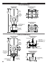
To install the LLS and LLSB Series,
a vertical mounting is recommended.
1. The unit threads directly into a 2 in. 11-1/2 NPT tee on the lead line.
2. Tighten the bottom housing to the lead line tee using ONLY the
transmitter wrench flats (see figure 1).
3. Check for leakage on any of the connections. Make sure that the
installation conforms with local and other applicable codes.
Connecting the LLSR and LLSRB Series
For mounting the switch enclosure refer to “Dimensions” on page 2.
The following instructions are based on the usage of a PD8187 Pulsation
Dampener option shown in Figure 2 (at right.)
1. Install sensor/pulsation dampener into pressure source connection.
2. Loosen the eight housing bolts until the bottom housing is free to turn.
3. Tighten the bottom housing to the pulsation dampener connection.
4. Tighten the eight housing bolts to 25±3 foot lbs. Stagger the tighten-
ing to assure even clamping.
5. Route capillary away from heat source (exhaust manifold). Excess
capillary should be carefully coiled and secured (do NOT cut it).
2 in. NPT
Use Wrech Flats to
Screw the LLS
Into the Process
Do NOT Tamper with
This Connection
Do NOT Tamper with
these Sealed Connections
Lead line tee
Wrench Flats
WARNING: PERFORM THE INSTALLATION WITH POWER SOURCE “OFF”. NEVER EXCEED RATED PRESSURE RANGE FOR THE UNIT.
USE WRENCH ON SHANK TO TIGHTEN/LOOSEN CONNECTIONS. DO NOT TWIST THE ENCLOSURE WHEN SCREWING THE LLS INTO THE
PROCESS – THIS WILL DAMAGE INTERNAL COMPONENTS, FILLED MECHANISM AND THE SEALS. DO NOT OVERTIGHTEN THE UNIT.
CAUTION: THE PD8187 PULSATION DAMPENER IS NOT INTENDED
AS A SHUTOFF VALVE. APPLY PIPE SEALANT TO THE THREADS.
CAUTION: DO NOT TAMPER WITH OR BREAK SEALED CONNEC-
TIONS. APPLY PIPE SEALANT TO PROCESS CONNECTION THREADS.
CAUTION: WHEN LOOSING THE EIGHT HOUSING BOLTS, MAKE
SURE NOT TO UNSCREW THE GREEN DIAPHRAGM CAPSULE.
Transmitting Tubing
(capillary)
Housing
Bolts
Diaphragm
Body
Pulsation
Dampener
(optional)
Wrench
Flats
Lead Line Tee
1 in. NPT
Figure 1
Figure 2
SPDT DPDT