


WARRANTY
A two year limited warranty on materials and workmanship is provided with this Murphy product. Details are
available on request and are packed with each unit.
4
LLS Series Trip Point Adjustment
if necessary (all models)
NOTICE: If trip point is not specified, the switch will be set at approx-
imately 50% of full scale. To perform trip point re-adjustments, a test
stand with variable pressure source, a test light, and a pressure gauge
(such as our OPLG or OPLFG MURPHYGAGE
®
) may be used.
To Reset for Rising Pressure
1. Locate and remove the Switch Trip Point Adjustment cover
(round) to reveal the Adjustment Wheel, (see figure 4).
2. After area is made non-hazardous, proceed to remove the square
cover to reveal the snap-switch(es).
3. Connect test light to (COM) and (N.C.) terminals. The light
should turn “ON”. Gradually increase the pressure until the light
turns“OFF”. Observe the trip point pressure reading.
4. With a screwdriver, turn the adjustment wheel to the desired setting.
Repeat step 4 until the light turns “OFF” at the desired pressure.
To Reset for Falling Pressure
Follow step 1 and step 2 (above), then:
3. Connect test light to (COM) and (N.O.) terminals. The light
should stay “OFF”. Gradually increase the pressure until the
light turns“ON”. Observe the trip point pressure reading.
4. With a screwdriver, turn the adjustment wheel to the desired setting.
Repeat step 4 until the light turns “OFF” at the desired pressure.
Replace the adjustment and the switch covers securely.
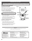
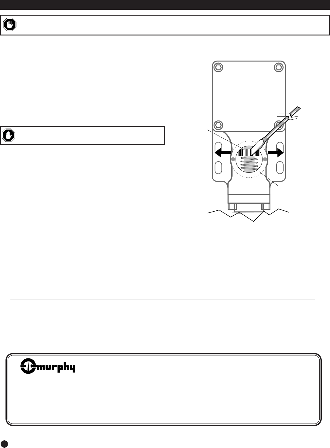
ADJUSTING THE TRIP POINT
To increase
set point
To decrease
set point
Adjustment
Wheel
Switch Trip Point
Adjustment Cover
or Round Cover
Snap-switch(es) Cover
or Square Cover
Do NOT remove until
the area is made
NON-HAZARDOUS
Screwdriver
CAUTION:
REMEMBER THAT THE FIELD-ADJUSTABLE TRIP POINT MAY HAVE BEEN FACTORY SET TO YOUR SPECIFICATIONS.
ADJUSTMENT OF THE TRIP POINT VARIES ACCORDINGLY TO THE APPLICATION AND MUST BE PERFORMED BY A QUALIFIED PERSON.
WARNING:
DO NOT REMOVE SNAP-SWITCH COVER AT THE
INSTALLATION SIGHT UNTIL THE AREA IS MADE NON-HAZARDOUS.
Figure 4
Printed in U.S.A.
®
FRANK W.
MFR.
■ Frank W. Murphy Manufacturer
P.O. Box 470248; Tulsa, Oklahoma 74147; USA
tel. (918) 627-3550 fax (918) 664-6146
e-mail fwmurphy@ionet.net
■ Frank W. Murphy Southern Division
P.O. Box 1819; Rosenberg, Texas 77471; USA
tel. (281) 342-0297 fax (281) 341-6006
e-mail murphysd@intertex.net
Since 1939
■ Frank W. Murphy, Ltd.
Church Rd.; Laverstock, Salisbury SP1 1QZ; U.K.
tel. +44 1722 410055 fax +44 1722 410088 tlx 477088
e-mail sales@fwmurphy.co.uk
■ Frank W. Murphy Pte., Ltd.
26 Siglap Drive; Republic of Singapore 456153
tel. +65 241-3166 fax +65 241-8382
e-mail fwmsales@fwmurphy.com.sg
■ Murphek Pty., Ltd.
1620 Hume Highway; Campbellfield, Vic 3061; Australia
tel. +61 3 9358-5555 fax +61 3 9358-5558
In order to consistently bring you the highest quality, full featured products, we reserve the right to change our specifications and designs at any time.
■ Murphy de México, S.A. de C.V.
Blvd. Antonio Rocha Cordero 300, Fracción del Aguaje
San Luis Potosí, S.L.P.; México 78384
tel. +52-48-206264 fax +52-48-206336
e-mail murmexsl@sanluis.podernet.com.mx
■ Murphy Switch of California
P.O. Box 900788; Palmdale, California 93590; USA
tel. (805) 272-4700 fax (805) 947-7570
e-mail sales@murphyswitch.com
■ Frank W. Murphy France
tel. +33 1 30 762626 fax +33 1 30 763989