


MDTM-8907N page 2 of 4
One Thermocouple Only
Even though the MDTM89 is a dual temperature monitor, it will monitor
and display one temperature with equal results.
When monitoring one temperature, always jumper the unused thermocou-
ple terminals on the back of the MDTM89 with a short length of wire.
The unused channel will display approximate ambient temperature.
Open Thermocouple Input
An open thermocouple input forces the monitor into upscale overrange.
The monitor indicates an overrange by displaying the numeral “1” in the
left most digit of the display. An overrange will turn on the trip point out-
put, for the respective thermocouple.
MDTM89 Wiring and Adjustment
Instructions
A. Using Thermocouple Extension Wire
1. After thermocouple installation, connect the thermocouple leads to
the MDTM89 according to the instructions.
IMPORTANT: Use correct wire for the thermocouple selected.
USE ONLY THERMOCOUPLE EXTENSION WIRE.
2. If the thermocouple leads are not long enough you will need to use
shielded thermocouple extension wire. The thermocouple extension
wires, from your thermocouple lead wires to the terminals of the
MDTM89, must be of the same material as the thermocouple lead
wires. (See Table 1.)
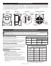
4-3/4 in.
(121 mm)
120
2-39/64 in. radius
(66 mm)
1/4 in.
(6 mm)
typical
diameter
120
4-3/4 in.
(121 mm)
4-1/4 in.
(108 mm)
4 in.
(102 mm)
5-1/2 in.
(140 mm)
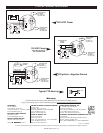
TC1
TC2
Screw for
Equipment Ground
Remove Jumper(s)
to Install
Thermocouple
Mount the MDTM89 temperature SWICHGAGE
®
in a place where it
will be protected from rain and splashing water. A minimum distance of
12 in. (305 mm) from any ignition coils or coil leads should be main-
tained. The MDTM89 flush mount case is intended for mounting in a flat
panel .032 in. (1 mm) to .125 in. (3 mm) thick.
First, cut a 4-
3
/4 in. (121 mm) diameter hole and three
1
/4 in. (6 mm)
diameter fastening holes as shown below. Insert the SWICHGAGE
®
from the back side of the panel. Using the three 10-24 screws, included
with the SWICHGAGE
®
, secure to the panel.
Mounting Hole Pattern
JJxWhite/Iron Red/Constantan
KKxYellow/Chromel Red/Alumel
Table 1. Thermocouple Extension Wire Color Code
Thermocouple
Type
Thermocouple
Extension Wire
Color Code/Material
Positive Lead Negative Lead
14 .07 .146
16 .137 .230
18 .222 .374
20 .357 .586
24 .878 1.490
Table 2. Thermocouple Extension Wire Loop
Resistance in Ohms per Foot at 68°F
Size
AWG No.
Type “J” Type “K”
Thermocouple lead length: 150 ohm lead resis-
tance affects monitor accuracy less than 1°.
Back View
Side View
Front View
MOUNTING DIMENSIONS
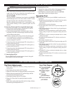
WIRING AND ADJUSTMENT INFORMATION
CAUTION:
Perform the wiring operation with the power source “OFF”. Make sure the voltage and current requirements are
within the SWICHGAGE
®
ratings. Keep all high voltage wiring, such as spark plug wires away from THERMOCOUPLES
AND EXTENSION WIRING. Before wiring determine the voltage and polarity for the application.