


MDTM-8907N page 3 of 4
3. When connecting the thermocouple extension wire to your thermo-
couple leads, twist the wire connections, then install wire nuts,
such as ceramic type, which have no metal insert.
DO NOT SOLDER.
To prevent problems of interference from electrical noise, DO NOT
route thermocouple wires in the same conduit or within 12 inches
(304 mm) of ignition wires or alternating current conductors.
Metallic-overbraided, thermocouple wire is recommended. It pro-
vides electrical shielding as well as protection against wear and
abrasion.
B. Connecting Thermocouple Wires (ungrounded thermocouple)
1. Remove factory installed jumpers or shunts from TC1 and TC2
terminals before connecting thermocouple(s).
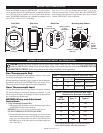
2. Connect the thermocouple leads to the thermocouples. Observe
lead polarity. See Table 1 for thermocouple extension lead color
code and thermocouple polarity.
NOTE: Before continuing to the next step, decide which thermocouple
is to be identified as TC1 and which is to be identified as TC2.
A wire marker should be installed on each end of the thermocou-
ple lead to identify TC1 and TC2.
3. Connect the positive lead of thermocouple TC1 to the positive (+)
terminal of terminal strip TC1.
4. Connect the negative lead of thermocouple TC1 to the negative (-)
terminal of terminal strip TC1.
5. Connect the positive lead of thermocouple TC2 to the positive (+)
terminal of terminal strip TC2.
6. Connect the negative lead of thermocouple TC2 to the negative (-)
terminal of terminal strip TC2.
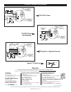
C. Connecting Output Wires
Wire the SWICHGAGE
®
trip point outputs as shown in the typical
wiring diagrams on the back of this page.
D. Connecting Power Wires
1. Determine the voltage and the polarity of the input power before
attempting to connect the power leads to the MDTM89.
2. On CD ignitions, connect the shutdown lead to the MDTM89
ignition input as shown in the diagrams below.
Operation Test
NOTE: Perform the Operation Test after the MDTM89 is installed and wired
appropriately.
1. a. Rotate the trip point potentiometers TC1 and TC2 clockwise until an
audible click is heard or detente is felt. These are 12-turn
potentiometers.
b. Start the engine or power up the monitor.
2. a. Set the display selector switch to the TC1 position to display the TC1
temperature.
b. Next depress and hold the “Push to Read” trip point push button to
display the TP1 setting.
c. Rotate the TC1 trip point potentiometer counterclockwise until the
display reading is equal to the temperature reading observed in
step 2. a.
d. Trip point TP1 will turn on and trip the shutdown device or alarm;
verify by observation.
e. Rotate the trip point potentiometer TC1 clockwise several turns to
turn off TP1.
f. Reset alarm or shutdown device.
3. a. Set the display selector switch to the TC2 position to display the TC2
temperature.
b. Next, depress and hold the “Push to Read” trip point push button to
display the TP2 setting.
c. Rotate the TC2 trip point potentiometer counterclockwise until the
display reading is equal to the temperature reading observed in
step 3.-a.
d. Trip point TP2 will turn on and trip the shutdown device or alarm;
verify by observation.
e. Rotate trip point potentiometer TC2 clockwise several turns to turn
off TP2.
f. Reset alarm or shutdown device.
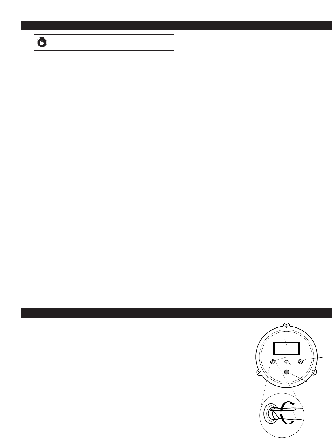
A
C
D
12 turn
potentiometers
DETAIL
B
Face Plate Diagram
A
. Trip point/display
toggle switch.
B
. Readout digital
display.
C
. Trip point
potentiometers.
D
. Push to read trip
point button.
WIRING AND ADJUSTMENT INFORMATION
TRIP POINT ADJUSTMENT INFORMATION
Trip Point Adjustments
1. Power up the temperature monitor by turning on power or by
starting engine.
2. Set the display selector switch to the TC1 position.
3. Depress the “Push to Read” trip point push button to read trip point.
4. Rotate the trip point potentiometer TC1 until the display indicates
the desired trip point temperature for TC1.
5. Set the display selector switch to TC2 position.
6. Depress the “Push to Read” trip point push button to read the
trip point.
7. Rotate the trip point potentiometer TC2 until the display indicates
the desired trip point temperature for TC2.
CAUTION:
The use of non thermocouple wire will cause
inaccurate temperature sensing and erratic operation.