


LM-92164N page 2 of 4
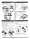
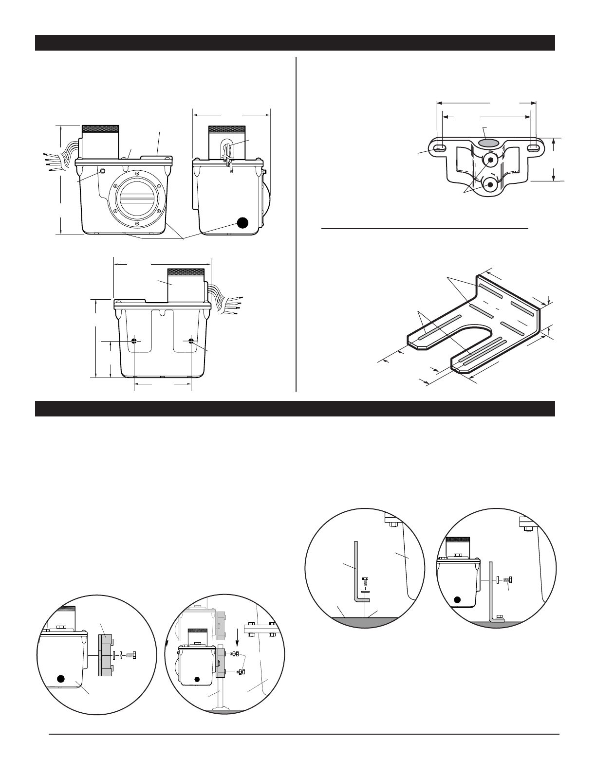
DIMENSIONS
TYPICAL INSTALLATION
8-1/4 in.
(210 mm)
Crankcase
Vent
1/2-14 NPT
Oil Inlet Connection
*
1/2-14 NPT
with removable
screen
6 in.
(152 mm)
Test
Knob
Electrical
Conduit
1/2-14
NPT
Monitoring Port Connection
3 places, 3/4-14 NPT
*
Applies to level maintaining models only.
7-3/16 in.
(183 mm)
5-3/16 in.
(132 mm)
3/8-16
UNC-2B
Mounting
Holes, 2 places
2-3/4 in.
(70 mm)
Snap Switch
Case Assembly
5-15/16 in.
(151 mm)
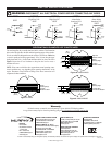
LM300 Series Enclosures
Mounting Brackets with Hardware
4.50 in.
(114 mm
)
5.20 in.
(132 mm)
2.
50
in
.
(
64 mm
)
H
o
l
e
.
88
in.
(
22 mm
)
dia
.
1/4-20 NC
2 places
.
3
7
6
in
.
(
10 mm
)
minim
u
m
bottom surface
2 places
1.75 in.
(44 mm)
7.50 in.
(191 mm)
Slot, .390 in. (10 mm)
x 4.71 in. (120 mm)
3 places
6.69 in.
(170 mm)
Slot, .390 in. (10 mm)
x 2 in. (51 mm)
4 places
4.50 in.
(114 mm)
5.19 in.
(132 mm)
15000371 pipe bracket
15000370 universal bracket
The dimensions below are for the optional -EX model enclosure. The
standard model enclosure dimensions are the same except the height and
width which are: 7 in. (178 mm) H, 7-7/8 in. (200 mm) W.
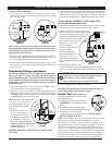
Mounting (all LM300 Series models)
NOTE: Mount the LM300 series level maintainers as close as possible
to the crankcase. Also, excessive vibration can cause overfill. Be sure
mounting brackets are supported.
The following instructions are based on the usage of the pipe and universal
mounting brackets shown above.
Pipe Bracket Mounting
1. Mount a nominal 1/2 inch (21 mm) diameter pipe to the deck of the engine.
2. Install the pipe bracket to the LM300 using two 3/8-16 UNC x 1 inch
bolts supplied. See Figure 1A.
3. Slip the LM300 onto the pipe and install the two adjustment bolts. Each
adjustment bolt consists of a 3/8-16 UNC x 1 inch bolt and two nuts. See
Figure 1B. DO NOT tighten the adjustment screws too tightly because
you will have to adjust the LM300 later in the installation process.
Mounting with Universal Bracket
The universal bracket has two mounting methods: deck mounting and
pan mounting.
Deck Mounting
1. Install the universal bracket to the deck as shown in Figure 2A with two
flat washers and two 3/8 inch (10 mm) diameter bolts (not supplied).
2. Mount the LM300 to the universal bracket using two 3/8-16 UNC x 1
inch (25 mm) bolts supplied (Figure 2B). DO NOT tighten the
adjustment screws too tightly. You will have to adjust the LM300 later in
the installation process.
Pipe
Crankcase
Adjustment
Bolts
Figure 1B
LM300
Pipe
Bracket
Figure 1A
Adjustment
Bolts
Figure 2B
Crankcase
Deck
Universal
Bracket
Threaded
hole
Figure 2A
Additional Hardware
Supplied
(4) 3/8-16 UNC x 1 inch
(25 mm) screws
(4) 3/8-16 nut
(4) 3/8 I.D. lock washer
(2) 3/8 I.D. flat washer
Additional Hardware
Supplied
(2) 3/8-16 UNC x 1 inch
(25 mm) screws
(4) 3/8 I.D. flat washer
(2) 3/8 I.D. lock washer
(2) 3/8-16 nut