


LM-92164N page 3 of 4
TYPICAL INSTALLATION continued
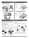
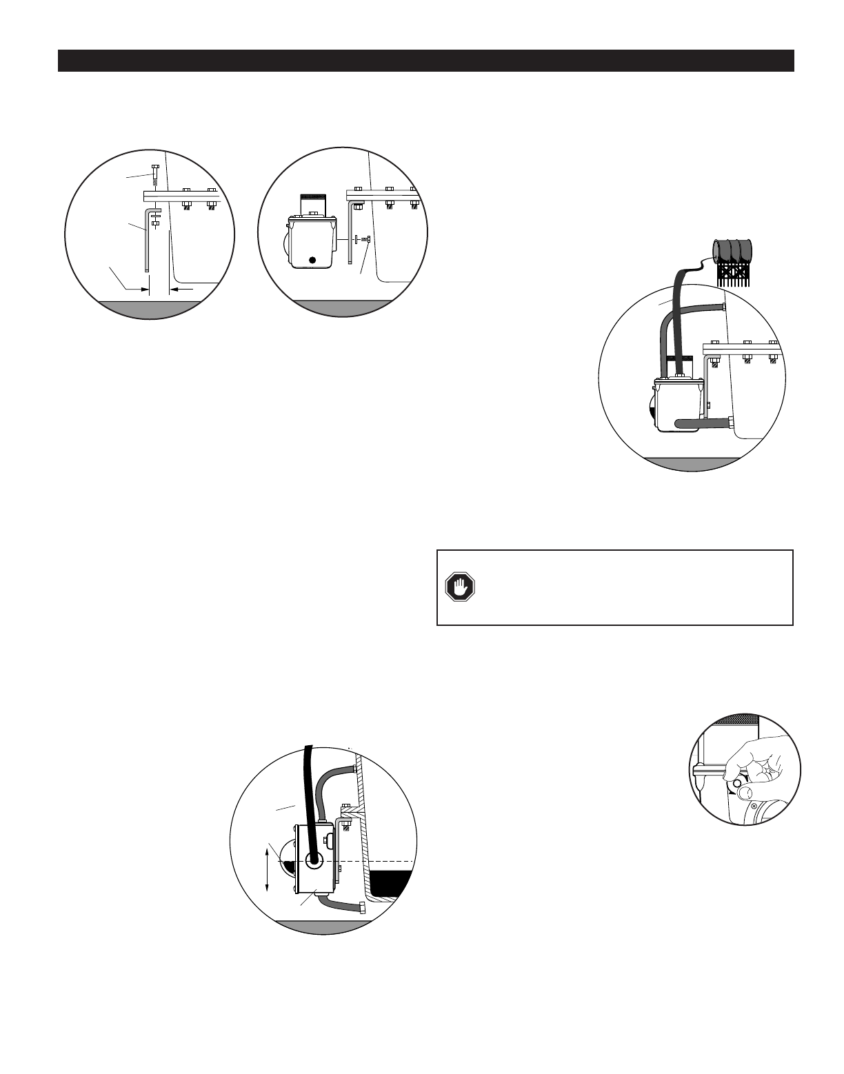
Crankcase (Oil Pan) Mounting
1. Install the universal bracket to the crankcase using the existing
crankcase bolts (Figure 3A). Crankcase bolt diameter must be no larger
than 7/16 inch (11 mm).
NOTE: Check clearance between crankcase and mounting bracket
before installing the mounting bracket. If space between the crankcase
and mounting bracket does not allow installation and access to the
adjustment bolts advance to Step 3.
2. Mount the LM300 to the universal bracket using two 3/8-16 UNC x 1
inch bolts supplied. DO NOT tighten the adjustment bolts too tight. You
will have to adjust the LM300 later in the installation process.
3. If space between the crankcase and mounting bracket is narrow, install
the universal mounting bracket to the LM300 before installing to the
crankcase oil pan.
Connecting Fittings and Hoses
The following instructions are for all LM300 series level maintainers.
All steps that reference oil inlet or oil supply tank DO NOT apply to
non-level-maintaining models. Also, these instructions are based on the
Murphy optional hose kit described on page 1. If you did not order the
optional hose kit, gather the hoses, clamps and fittings as specified in
the optional hose kit.
1. Install the LM300 fittings in their proper locations. NOTE: Apply a
sealant such as teflon, to all threaded connections.
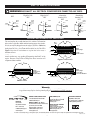
2. Attach the 1 inch (25 mm) diameter, flexible monitoring hose to the
crankcase and the monitoring port on the LM300. See Figure 4.
CAUTION: The hose must slope slightly downward from the LM300
and MUST NOT have any droop or low spots.
NOTE: If the drain plug on the crankcase
is used for the connection, we
recommend installation of a tee to
allow draining of the crankcase
for service.
3. Install the 1/2 inch (13 mm)
I.D. x 3 ft. (914 mm) hose to
the vent connection on the
LM300 to the vent connection
on the crankcase. See Figure 4.
The vent connection on the
crankcase must be well above the
regulated oil level. All hoses must
be clear of obstructions.
BEFORE CONTINUING, VERIFY THAT ALL HOSE CLAMPS
ARE TIGHT.
4. Fill the crankcase to the proper oil levels. With the engine running and
warm, loosen the mounting bracket adjustment bolts and adjust the
LM300 so that the oil level in the sight gauge is aligned with the white
“index line” on the dial (Figure 4). Tighten the adjustment bolts securely.
Connecting the LM300 to an Oil Supply Tank
(level maintaining models only)
1. Remove the caplug from the oil inlet connection. Be sure the filter, inside
the connection, is clear of debris. Install the oil inlet connection.
2. Connect a 1/2 inch I.D. (13 mm) or larger hose
to oil inlet fitting on the LM300 and to the shutoff
valve on the oil supply tank. See Figure 5. For
models LM300 thru LM305 recommended
minimum mounting of the oil supply
tank above the LM is 4 ft. (1.2m);
maximum 15 ft. (4.6m). The
hose must maintain a
downward slope and not have
low spots or droops.
Maximum head pressure
rating using standard 1/4 in. (6
mm) orifice is 15 ft. (4.6
meters). See Flow Rate test on
page 1 for additional orifice pressure
ratings.
3. Before filling the supply tank with
oil, be sure the tank is clean and dry andthe shutoff valve is closed.
Also, be sure all hoses and clamps are tight. Fill the tank with CLEAN
oil.
4. After oil supply tank is full, open the shutoff valve.
Next, make the proper electrical connections for the application. See
contact ratings on page 1 and schematics on page 4.
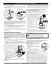
Switch Test
(switch models only)
To test the shutdown and/or alarm functions
perform the following:
1. Unscrew protective boot from test knob.
IMPORTANT: Always replace boot after
testing.
2. Turn the test knob 1/4 turn to the right
(clockwise), for low test indication (Figure 6).
3. Turn the knob 1/4 turn to the left
(counterclockwise), for high test indication. DO NOT FORCE
THE TEST KNOB TO TURN.
NOTE: After the engine shuts down, you will notice that the oil in the
sight gauge glass will rise above normal running level, possibly
showing an overfill condition. This is a result of “drain-back” to the
engine crankcase and it is normal. Therefore, on models LM302 and
LM303 it may be necessary to wire the high level shutdowns into a
class “B” or “C” (bypass until first time safe) lockout, so as to allow a
permissive start. After the engine is re-started the level will pull down
to the normal running level and the shutdown features will be active. A
modulating valve (Thumb-Valve™) in the level maintaining models
will allow oil usage to be made-up continuously during operation.
Adjustment
Bolt
Figure 3B
Crankcase
Universal
Bracket
Crankcase
Bolt
Note Clearance
before mounting
Figure 3A
Viewing
Lens
Monitoring Hose
Crankcase
Oil Level
Running
Engine
Vent
Hose
Oil Inlet
Hose
Figure 4
Oil Inlet
Hose
Oil Supply
Tank
Figure 5
Figure 6
WARNING: Overfill condition can be caused by excessive
inlet pressure, (maximum inlet pressure depends on orifice),
and/or improper “vent to crankcase” installation.
See Flow Rate Test on page 1 for maximum pressure.