


INSTALLATION
2
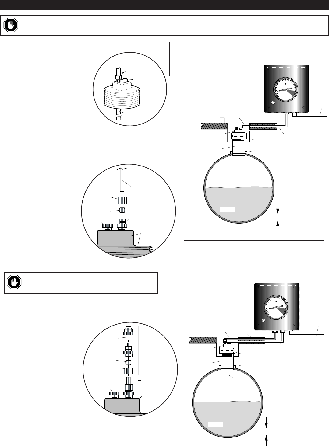
Installing a Tank Plug Kit (all models)
The tank plug kit includes 12 ft. (3.6 m) x 1/4 in.
(6 mm) dia. stainless steel tube and fittings.
Tank plug is available in 2 NPT or 4 NPT.
1.
Locate tank(s) service cover and install
a UTKN tank plug kit for each tank.
Necessary hardware is available from
Murphy, refer to “Service Parts and
Accessories” section, on page 4.
2.
Route a tubing line (1/4 in. [6 mm] out-
side dimension) from the tank top to the
panel location. If applicable, cut a channel in the
driveway surface to route the tubing. The use of rigid conduit is recom-
mended especially when routing the tubing line under a driveway surface.
Refer to Fig. 1, at right.
3.
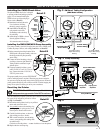
Before inserting the 1/4 in. (6 mm) dia.
stainless steel tubing (probe) through tank
plug fitting, make sure tubing can reach
bottom and also will allow extra tub-
ing for adjustments. Now lower the
tubing until it touches the bottom
of the tank, do this as follows
(refer to Detail A, at right):
A. First, loosen ferrule and ferrule
fitting nut.
B. Insert the tubing through the
ferrule nut and fitting.
C. Mark tubing at top of fitting–raise tub-
ing exactly 3 in. (76 mm) off bottom and
finger tighten ferrule and compression nut.
D. Cut excess stainless steel tubing allowing 1/2 in. (13 mm) extension
above the compression nut.
4.
Connect tubing line to tank probe as shown
(refer to Detail B, at right).
5.
Now connect other end of tubing line
to the SM/SMVR gage panel fit-
ting. Tubing should be continuous
length without splices.
6.
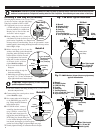
For SMVR models, connect a
second line from the tank top (if
using UTKN kit, remove Hole
Plug and install second sensor fit-
ting and line) to the SMVR gage 1/8
NPTF fitting line. Second sensing line
is to be installed through the tank top and
into the tank, but keep the tip of the line above
product level (refer to Fig. 2, at right and Fig. 3, next page).
7.
Securely tighten all fittings; all connections must be air tight.
A
B
C
D
E
F
G
Steel Tube Located
3 in. (76 mm) Off
Bottom (typical)
A. Manwell
B. Driveway Surface
C. UTKN Tank Plug
D. Coupling
E. Stand-Pipe
F. Tank Plug Opening
G. 1/4 in. (6 mm) dia. Steel Tube
Product
SM1 Model
Below ground
tank (vented)
Tubing
To Pump
Assembly
FEET
MURPHY
LEVELGAGE
A
B
C
D
E
F
G
H
Steel Tube Located
3 in. (76 mm) Off
Bottom (typical)
A. Manwell
B. Driveway Surface
C. UTKN Tank Plug
D. Coupling
E. Stand-Pipe
F. Tank Plug Opening
G. 1/4 in. (6 mm) dia. Steel Tube
H. Vapor Recovery Line
Product
Below ground
tank (vented)
Keep tip of
line above
product level
Vapor Recovery
Tubing
Tubing
SM1 Model
To Pump
Assembly
FEET
MURPHY
LEVELGAGE
UTKN Tank Plug
or tank top
1/2 in. (13 mm)
Ferrule
Tubing
Tubing Fitting
(2 included)
Compression
Nut
Hole Plug
Fig. 2
SMVR Series (Vapor Recovery Systems)
typical Installation
Fig. 1
SM Series Typical Installation
CAUTION:
Excessive tightening of ferrule fittings will
prohibit re-adjustment if necessary.
1/4 in. (6 mm) dia.
304 Stainless Steel
tubing (probe);
12 ft. (3.6 m) long
Compression
Nut
Ferrule
Hole Plug
Sensor Fitting
UTKN
Tank Plug
WARNING: Installation of the SM and SMVR Series MUST BE made by qualified installer. Hazardous conditions exist with flam-
mable and corrosive products. Extinguish all smoking materials. Risk of explosion, fire and burning can cause serious or fatal injury.
Vapor Recovery
connection (plugged)
Tubing
Connection
1/4 x 12 ft. (3.6 m)
Steel Tubing
Tank Plug
Detail A
Detail B