


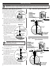
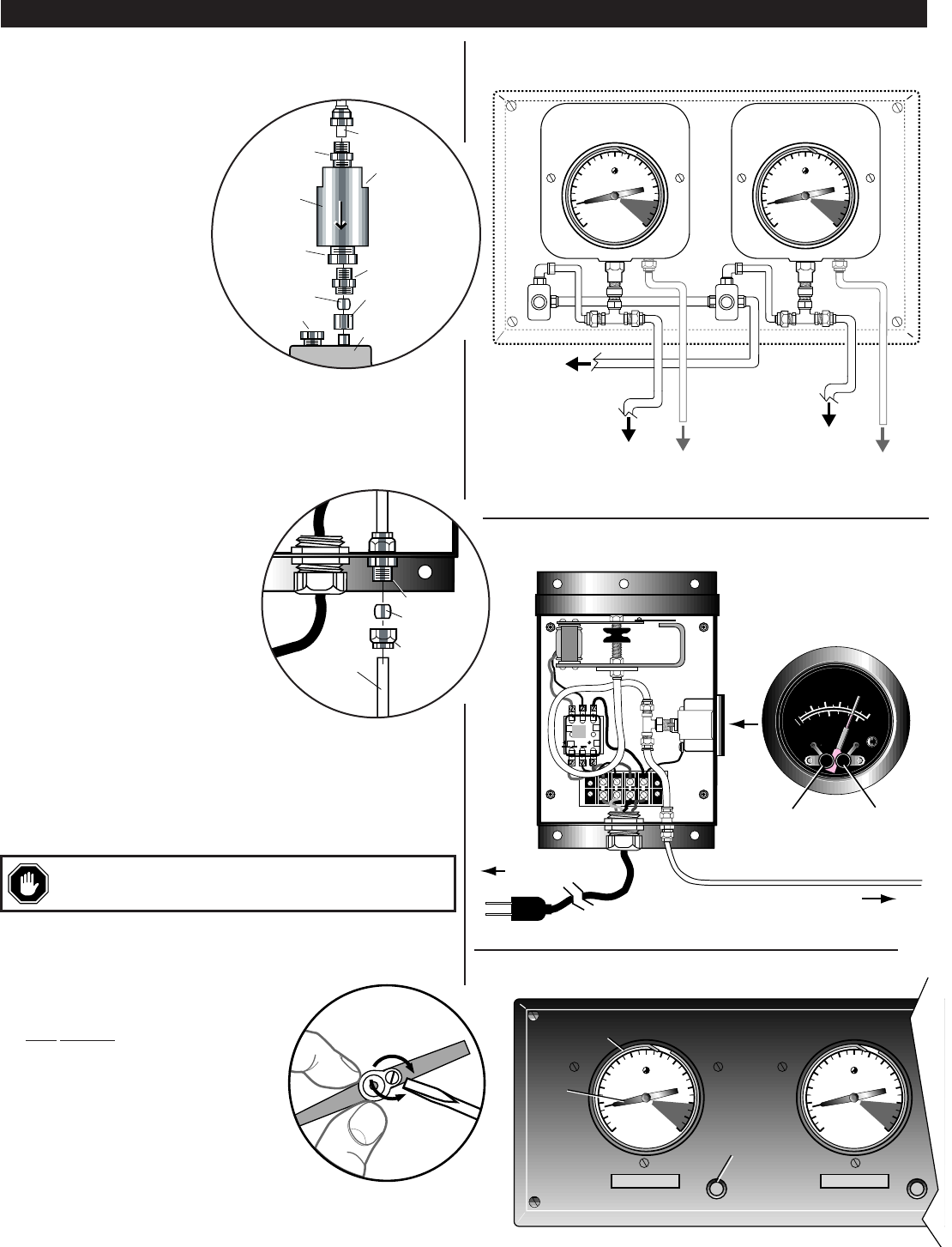
Installing the CKBO Check Valve
The optional CKBO check valve is designed
to prevent product from backing up into the
gage(s). We recommend installing the
CKBO valve at top of the tank plug as
follows (refer to Detail C):
1.
Determine a location for the valve.
Use of sealant on all fitting
threads is strongly suggested.
2.
Attach CKBO to the tank plug
using wrench on valve flats.
See markings on the valve body
for positioning.
3.
Attach tubing to CKBO as shown.
Securely tighten all fittings.
All connections must be air tight.
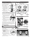
Installing the SMPA/SMPA230 Pump Assembly
The pump assembly should be installed near the SM or SMVR panel.
Connect the pump as follows (refer to Fig. 3 and 4 also see Detail D):
1.
Before connecting the tubing from the SM or
SMVR panel to the pump assembly, make sure
the tubing reaches the pump assembly
sensor fitting.
2.
Connect the end of the tubing to the sen-
sor fitting as shown at right (Detail D).
Tubing should be continuous length
without splices.
3.
The pump assembly includes a power
cable, 16 AWG (1.5 mm
2
), 8 ft. (2.4 m)
long. Connect the cable to 120 VAC or
230 VAC power source.
The pump assembly has a pressure SWICHGAGE
®
with low and high pressure set points. When the gage pointer reaches the
low pressure set point, the pump starts to built up purge pressure. When the
pointer reaches the high set point, sufficient volume is reached stopping the
pump. The set points are factory pre-set for your convenience.
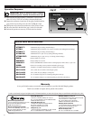
Resetting the Pointer
After the SM/SMVR complete system has been connected, reset the pointer
for proper level indication, proceed as follows
(see Fig. 5 and Detail E):
1.
Determine actual product level by any reliable
means and record this value.
2.
Very carefully remove the retaining ring
guarding against its spring-action, it can
cause injuries. Remove the lens also.
3.
Carefully hold the pointer, as shown at
right, making sure not to bend it.
4.
With a small screwdriver, turn the setting
screw to corresponding stick reading value
recorded in step 1.
Clockwise to raise the pointer — counter clockwise to lower the pointer.
5.
Replace the lens and snap ring.
INSTALLATION
Continued
3
To Tank 1 Plug
Sensor Fitting
To Tank 2 Plug
Sensor Fitting
SM Panel (SM2 Model Shown)
To Tank 1 Plug
Vapor Recovery
Fitting
To Tank 2 Plug
Vapor Recovery
Fitting
To Pump
Assembly
FEET
MURPHY
LEVELGAGE
FEET
MURPHY
LEVELGAGE
120 VAC or 230 VAC
Tubing to SM Panel
Pressure SWICHGAGE
®
kPa
PRESSURE
0
100
20
40
60
0
300
80
600
PSI
M
U
R
P
H
Y
S
W
I
C
H
G
A
G
E
®
Low trip point
adjustment
High trip point
adjustment
Fig. 4
Pump Assembly
Tubing
Power
Cable
Compression
Nut
Ferrule
Sensor Fitting
Pump
Panel
Detail D
Read Button
SM Panel (SM2 Model Shown)
FEET
MURPHY
LEVELGAGE
FEET
MURPHY
LEVELGAGE
Pointer
Snap Ring
UNLEADED UNLEADED
Turn to Lower
the Pointer
Turn to Raise
the Pointer
CAUTION:
SM and SMVR models are precalibrated in feet of
static pressure above gage connection. Pointer MUST be reset to zero.
Detail E
Tubing
Check
Valve
Valve
Flat
1/4 NPTM
straight
fitting
1/4 NPTM
straight fitting
Ferrule
Ferrule nut
1/2 NPTM to
1/4 NPTF
Reducer
UTKN Tank Plug
or tank top
Hole Plug
T
A
N
K
Detail C
Fig. 3
SM Panel Tubing Configuration
(SM2 Model shown)
Fig. 5