


ST-94112N page 3 of 4
ELECTRICAL
A
B
Battery
Run
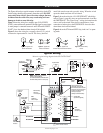
Remove jumper from
terminals 12 and 13 and
set individual sensor Lockout
Switch for a 25 to 35 second
lockout time delay during
startup (see page 4
Setting Lockout Switches).
Sensor Lockout Switches
5
91310 11 12 14
A
B
6
A
B
7
A
B
A
B
A
B
A
B
A
B
8
1
2
3
4
No Connection
No Connection
No Connection
ON/OFF
Switch
Internal Relay
(shown in
run mode)
Jumper Wire
(customer supplied)
Engine Oil
Pressure
ST8
Shutdown
Sensor Inputs
ST8
Shutdown
Sensor Inputs
Push/Pull Solenoid
Solenoid Valve
Slave Relay
Start
Pushbutton
Coil
Distributor
Starter
Motor
To Battery +
2 Amp
Fuse
Flyback
Diode
Flyback
Diode
Flyback
Diode
Flyback Diode
To Hold Coil
NOTE: Connect only one shutdown
device to the ST8. Wiring
for Push/Pull Solenoid, Solenoid Valve
and Slave Relay shown for clarity only.
To Pull-in Coil
Engine Water
Temperature
Low
Water
Level
Differential
Pressure
No Connection
ON
1
2 3 4 5 6 7 8
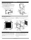
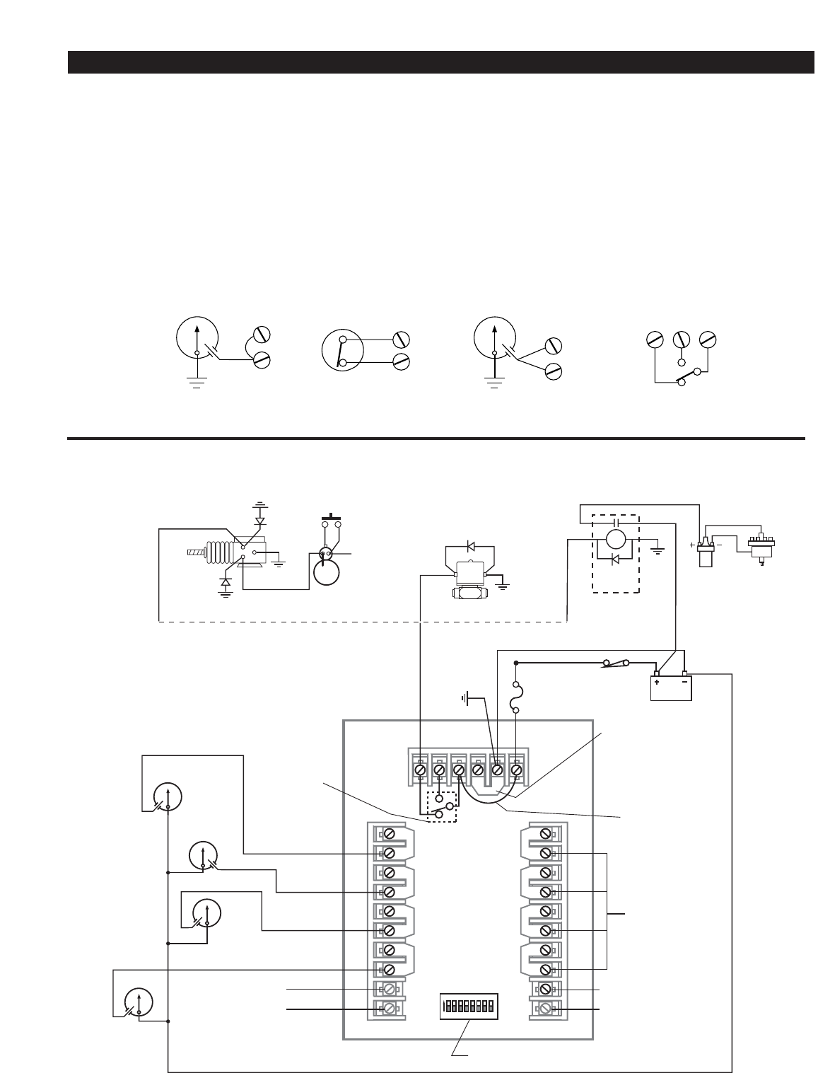
The Figures below show typical customer switch wiring for the ST8.
Switch wiring should be run separately from other wires; DO NOT
route switch wires with AC power wires since voltages, that may
be induced into the switch wires, may exceed rating and cause
damage to circuits or cause false trips.
Figure 1 shows the wiring for a normally open (N.O.) SWICH-
GAGE
®
connected between terminal B and the negative power input.
A metal jumper is connected between A and B. When the SWICH-
GAGE
®
closes the shutdown/alarm circuit will be initiated.
Figure 2 shows the wiring for a normally closed (N.C.) switch
connected to input terminals A and B. The factory installed
metal link must be removed to use this wiring. When the switch
opens the shutdown/alarm will be initiated.
Figure 3 shows the wiring for a N.O. SWICHGAGE
®
which is the
same as Figure 1 except two wires are run from terminals A and B to
the SWICHGAGE
®
. This Closed Loop™ wiring circuit monitors the
wires as well as the switch. If the circuit is opened due to a loose
connection or broken wire or the SWICHGAGE
®
closes, the shut-
down/alarm circuit will be initiated.
Figure 4 shows the ST8 internal SPDT relay in the “run” or operat-
ing mode.
Typical Wiring
Below is a typical wiring diagram for the ST8 TATTLETALE
®
.
A
B
A
B
A
B
9
N.O. N.C. C
10 11
Figure 1: Typical N.O.
Sensor Connection
Figure 2: Typical N.C.
Sensor Connection
Figure 3: Typical N.O.
Closed Loop™ Sensor Connection
Figure 4: Internal Relay
Circuit