


English
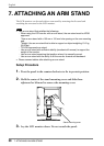
26 5. CALIBRATION
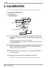
5. CALIBRATION
The calibration is available when using the specified optional calibration kit (p.38).
Accessories for Calibration Kit
• Photo Sensor x 1
• Maintenance cable x 4
• Calibration Software
1. Confirm the graphics board settings (If the graphics board has the
settings below). Please read the User’s manual of the graphics board
in details.
• Set the output signal level to “Linear” or "Static Gray".
• Release the “Setup (i.e. the function to up to the black level)” when using the
analog graphics board.
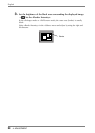
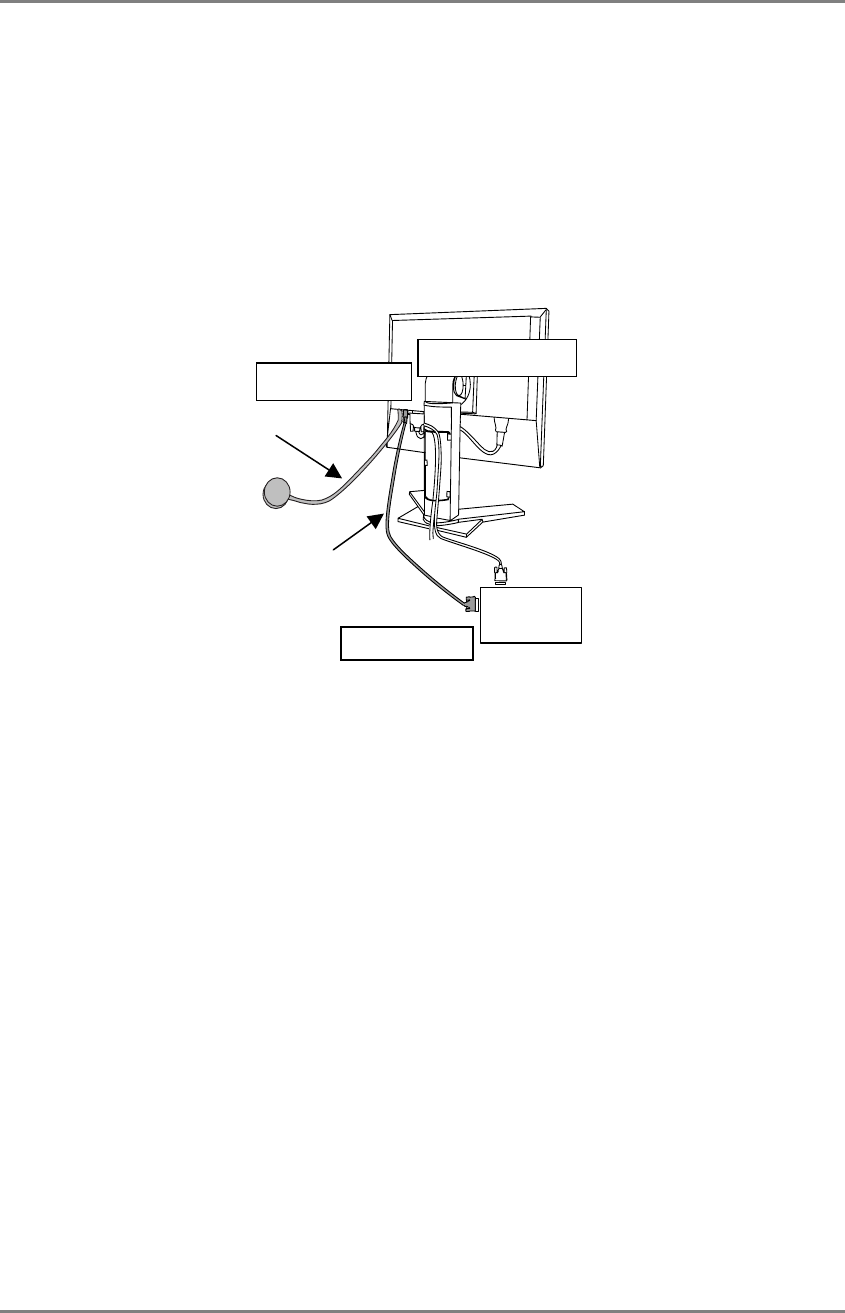
2. Plug the maintenance cable into the REMOTE IN (Mini DIN 6 pin)
connector of the monitor and the other end of the cable into the
serial port (D-Sub 9 pin) of the PC.
3. Plug the photo sensor to the photo sensor connector (Mini DIN 8
pin) of the monitor.
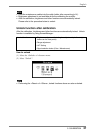
4. Install the calibration software and calibrate the monitor.
About the directions (for use), please read the user’s manual of the software.
Maintenance cable
PC
Mini DIN 6 pin
Photo Sensor
D-
Sub
9
p
in
Mini DIN 8 pin