


33
Chapter 5 Reference
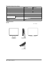
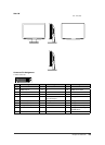
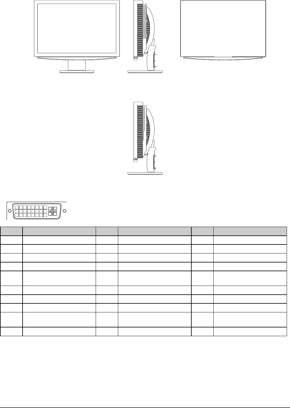
S2411W
unit : mm (inch)
Connector Pin Assignment
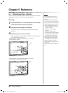
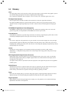
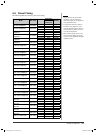
• DVI-I connector
1
2
3
4
5
6
7
8
9
10
11
12
13
14 15
16
19
20
2117
18 22 23
24
C1
C2
C3
C4
C5
Pin No.
Signal
Pin No.
Signal
Pin No.
Signal
1 TMDS Data 2- 11 TMDS Data1/3 Shield 21 NC*
2 TMDS Data 2+ 12 NC* 22 TMDS Clock shield
3 TMDS Data2/4 Shield 13 NC* 23 TMDS Clock+
4 NC* 14 +5V Power 24 TMDS Clock-
5 NC* 15 Ground (return for +5V,
Hsync and Vsync)
C1 Analog Red
6 DDC Clock (SCL) 16 Hot Plug Detect C2 Analog Green
7 DDC Data (SDA) 17 TMDS Data0- C3 Analog Blue
8 Analog Vertical Sync 18 TMDS Data0+ C4 Analog Horizontal Sync
9 TMDS Data1- 19 TMDS Data0/5 Shield C5 Analog Ground (analog
R,G,&B return)
10 TMDS Data1+ 20 NC*
(NC*: No Connection)