


32
Chapter 5 Reference
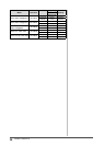
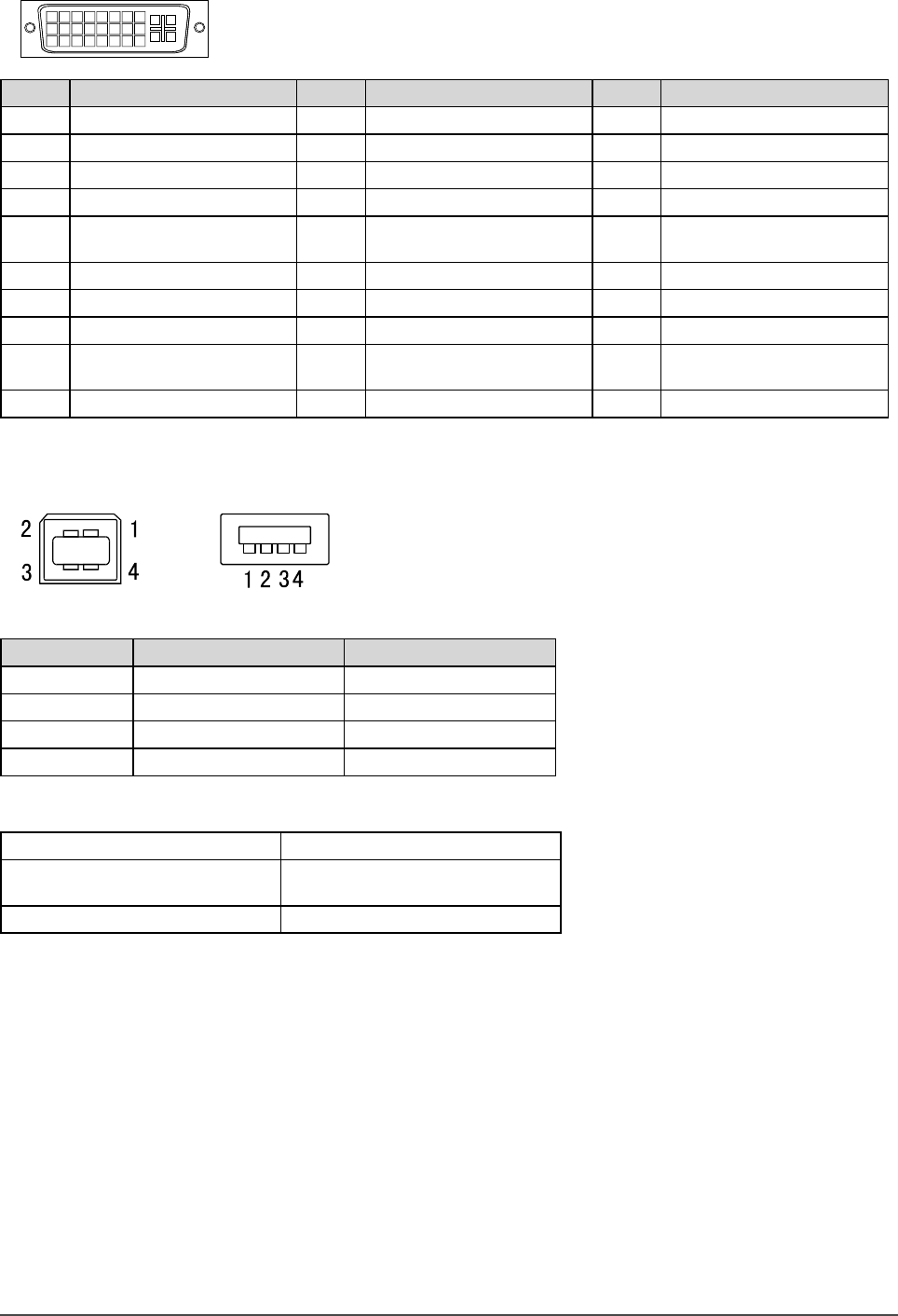
Connector Pin Assignment
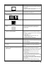
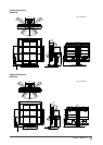
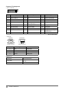
• DVI-I connector
1
2
3
4
5
6
7
8
9
10
11
12
13
14 15
16
19
20
21
17
18 22 23
24
C1
C2
C3
C4
C5
Pin No.
Signal
Pin No.
Signal
Pin No.
Signal
1 T.M.D.S. Data 2- 11 T.M.D.S. Data1/3 Shield 21 NC*
2 T.M.D.S. Data 2+ 12 NC* 22 T.M.D.S. Clock shield
3 T.M.D.S. Data2/4 Shield 13 NC* 23 T.M.D.S. Clock+
4 NC* 14 +5V Power 24 T.M.D.S. Clock-
5 NC* 15 Ground (return for +5V,
Hsync and Vsync)
C1 Analog Red
6 DDC Clock (SCL) 16 Hot Plug Detect C2 Analog Green
7 DDC Data (SDA) 17 T.M.D.S. Data0- C3 Analog Blue
8 Analog Vertical Sync 18 T.M.D.S. Data0+ C4 Analog Horizontal Sync
9 T.M.D.S. Data1- 19 T.M.D.S. Data0/5 Shield C5 Analog Ground (analog
R,G,&B return)
10 T.M.D.S. Data1+ 20 NC*
(NC*: No Connection)
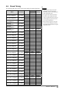
• USB port
Upstream
Series B connector
Downstream
Series A connector
Contact No. Signal Remarks
1 VCC Cable power
2 – Data Serial data
3 + Data Serial data
4 Ground Cable ground
Option List
Cleaning Kit EIZO ScreenCleaner
Signal Cable
FD-C16
FD-C39
Speaker Unit i•Sound L3