


17
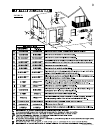
W415-0583 / A / 01.09.07
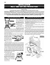
Optional Front
Glass Door
Latches
Retainer
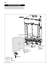
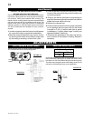
Before the glass door can be removed, the optional front
must be removed.
The glass door is secured to the top front edge of the fi rebox.
Pull the handles of the latches forward, then lift the hooks out
from the slots in the door frame to release the top of the door.
Next, pivot forward until the top edge of the door clears the
front of the fi replace. Next gripping the sides of the door lift
the door out from the retainer along the bottom of the door.
FIGURE 34
DOOR REMOVAL
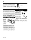
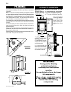
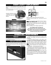
REMOTE, RECEIVER AND VALVE ACCESS
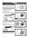
1a. Rectangular Front Removal
Pull on the top of the optional front away from the fi replace until
the male portion of the latch disengages. Tilt forward slightly
and lift from the 2 shoulder screws near the bottom.
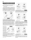
1b. Heritage and Wrought Iron Front Removal
Turn the head of each turn button from a horizontal position
to vertical. (Fig. 41) Allow the front to tilt forward slightly
and lift from the 2 shoulder screws near the bottom front.
Note: Fronts are heavy so when the second turn button
is turned the front will want to fall forward.
BURNER ASSEMBLY REMOVAL
FIGURE 41
2. Control Panel Removal
Lift the panel from the slots. This will allow access and removal
of the remote receiver and spark module.
If valve replacement is necessary follow step 1 above then
proceed with the following ...
3. Door Removal
The glass door is secured at the top front edge of the fi replace.
Pull the latch forward then lift hook out from slot in the door.
Pivot door forward then lift out from retainer along the bottom
edge of the fi rebox.
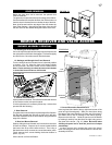
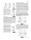
4. Bowl and Burner Removal
Start by sliding the bowl forward until it clears the buner then
lift from the fi rebox. Remove the 2 screws located behind
the burner then lift up off the orfi ce and out. Then using a
fl at head screw driver remove the curved decorative panel.
Finally remove the 2 screws holding the burner bottom in
place. (Fig. 42)
Lift the burner out from the fi rebox.
TOP
EDGES
BOTTOM
EDGES
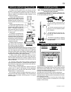
5. Curved Decorative Panel Removal
Insert a gloved hand behind the top right hand corner of the
panel and pull forward gently. Slide your hand down along
the edge of the panel allowing it to come out of its place in
the fi rebox and to rest on the edge of the fi rebox opening.
Repeat on the left. side. Guide the panel out of the fi rebox
by rotating it carefully from the left to the right, being sure to
stay clear of the burner. (Fig. 41) Note: Be careful when
bending the panel not to bend the panel out of shape
perminately.
6. Next, remove the 6 screws that secure the burner
base. Once the gas has been disconnected, the burner train
assembly will lift out.
FIGURE 42