


cFP-2200/2210/2220 24 ni.com
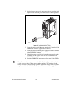
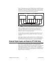
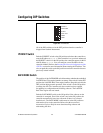
You can use the two digital inputs to control the cFP system from
LabVIEW. For example, one input could be a START/STOP switch, and
the other could determine which of two VIs should run at startup. NI
recommends connecting a single-pole single-throw (SPST) switch between
the input terminal and one of the C terminals. The inputs have a value of 1
when the switch is closed and 0 when the switch is open.
Figure 28. Wiring the cFP-2220 External Input and Output Terminals
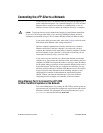
Connecting USB Mass-Storage Devices to the cFP-2220
The cFP-2220 supports common USB mass-storage devices such as USB
Flash drives. You can connect USB mass-storage devices to the cFP-2220
while the controller is operating. USB devices are mapped to the
U: drive
in LabVIEW. The cFP-2220 does not support other types of USB devices.
Refer to the LabVIEW Real-Time Module Help for more information.
Caution Do not hotswap USB devices while the Compact FieldPoint system is in a
hazardous location or connected to high voltages.
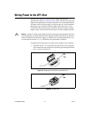
Using the Internal Real-Time Clock
The system clock of the cFP-22xx gets the date and time from the internal
high-precision real-time clock at startup. This synchronization provides
timestamp data to the controller. You can also use the internal real-time
clock to correct drift of the system clock. Please contact National
Instruments for more information.
C
C
O2
C
O1
LED B
C
I2
I1
LED A
R2
R1
Switch 2
Switch 1