


© National Instruments Corporation 9 cFP-2200/2210/2220
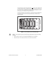
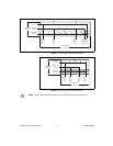
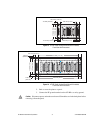
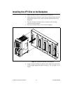
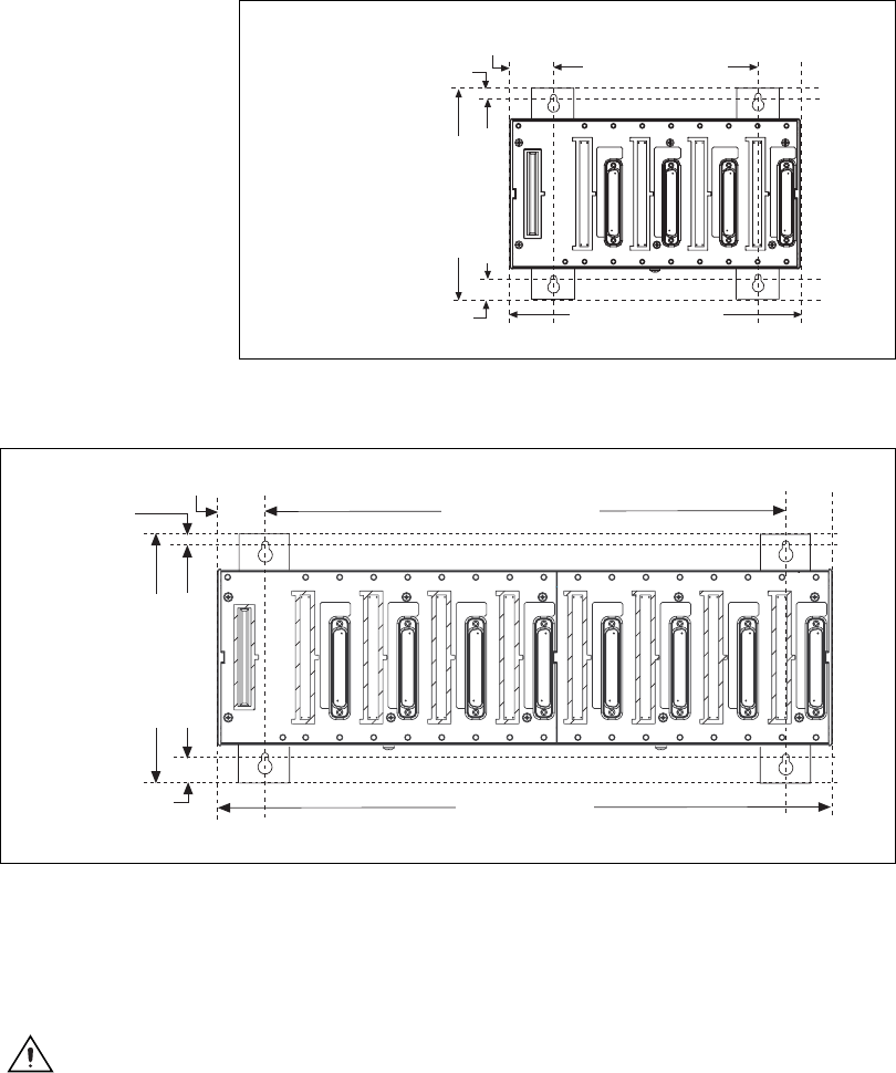
Figure 13. cFP-BP-4 with Vertical Panel-Mount Kit Installed,
Front View with Dimensions
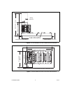
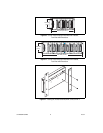
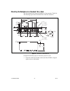
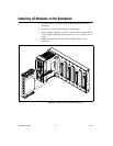
Figure 14. cFP-BP-8 with Vertical Panel-Mount Kit Installed,
Front View with Dimensions
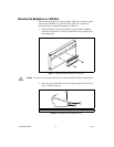
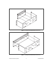
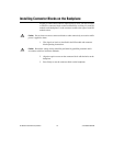
2. Bolt or screw the plates to a panel.
3. Connect the PE ground terminal on the cFP-BP-x to safety ground.
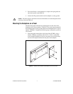
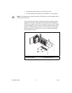
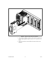
Caution Disconnect power and make sure that no I/O modules are in the backplane before
removing it from the panel.
178 mm (7 in.)
152 mm (6 in.)
246 mm (9.7 in.)
178 mm (7.0 in.)
34.0 mm (1.34 in.)
7.6 mm (0.30 in.)
17.8 mm (0.70 in.)
457 mm (18 in.)
374 mm (14.7 in.)
178 mm (7 in.)
152 mm (6 in.)
33.1 mm (1.31 in.)
7.6 mm
(0.30 in.)
17.8 mm
(0.70 in.)