


© National Instruments Corp. 3 FP-RTD-122 and cFP-RTD-122
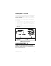
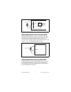
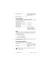
To install the cFP-RTD-122, refer to Figure 2 and complete the
following steps:
1. Align the captive screws on the cFP-RTD-122 with the holes
on the backplane. The alignment keys on the cFP-RTD-122
prevent backward insertion.
2. Press firmly to seat the cFP-RTD-122 on the backplane.
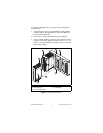
3. Using a number 2 Phillips screwdriver with a shank of at least
64 mm (2.5 in.) length, tighten the captive screws to 1.1 N ⋅ m
(10 lb ⋅ in.) of torque. The nylon coating on the screws prevents
them from loosening.
Figure 2. Installing the cFP-RTD-122
1 cFP-RTD-122
2 Captive Screws
3 cFP Controller Module
4 Screw Holes
5 cFP Backplane
2
2
1
3 5
4
4